
Wellington Mk III
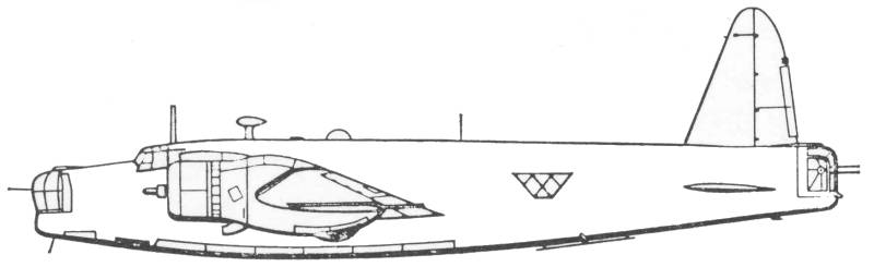
The Vickers Wellington enjoyed a long and distinguished career during World War II. Used in combat at the very outset of the war, it carried the brunt of the RAF Bomber Command's night bombing offensive until the operational debut of the first four engine heavies and was still first line equipment at the end of the war. The Wellington's docile handling and lively performance, for the time, and its ability to absorb a fantastic amount of battle damage rapidly endeared it to its crews. More than any other bomber the Wellington proved the power operated turret to be a formidable defensive weapon and it also disproved the widely held belief that large bombers could undertake daylight bombing attacks against heavily defended targets without fighter escort.
The Wellington's ability to absorb battle damage is attributed to the geodetic system of construction conceived by Barnes Wallis and first used on the Vicker's Wellesley, which was built as a private venture. The prototype, after some vacillation over what power plant would be used finally took to the air on June 15, 1936. Although destined to be completely redesigned before emerging as the Wellington I, it was a major step forward in British bomber design. The first production Wellington I took to the air on December 23, 1937. The Wellington IA was first flown in 1939 had revised armament consisting of Nash and Thompson hydraulic turrets in the nose and tail and a ventral position with two .303 caliber gun in each. Sound proofing was introduced in the cabin, an astrodome was fitted, a fuel jettison system with discharge pipes under the the wings and larger wheels, which now protruded from their housings when retracted were added do to increases in the overall weight. No IB version was built, the next, the IC had a 24V electrical system in place of the 12V system and the ventral turret was replaced by by two Vicker's "K" guns mounted to fire from positions on either side of the fuselage.
To protect against problems in obtaining the Pegasus radial engines the Wellington II and III were produced, the II having Rolls-Royce Merlins and the III having Bristol Hercules air cooled radials. The II flew for the first time in March of 1939 and the III in May of 1939. A Wellington IV was built with yet another alternative power plant the Pratt and Whitney R-1830. The Wellington III was phased into service in 1942 together with the Mks. II and IV and provided the mainstay of Bomber Command while operational strength of the heavy bomber units was being built up. A slightly improved version the Wellington X went into production in 1943 and was built in larger quantities than any other version with 3,500 examples being built compared to 1,500 Mk. III's and and over 2,500 MK.IC's. The primary difference between the Mk. III and MK. X was more powerful engines.
The last Wellington built was delivered in October of 1945, total production was 11,461 aircraft. The Wellington served in most of the operational theaters in which the RAF was engaged. It performed a remarkable diversity of roles probably unequaled by any other bomber of the Second World War and its unique geodetic structure endowed it with a ruggedness that was enjoyed by no other twin engine bomber of its period.
The Kit
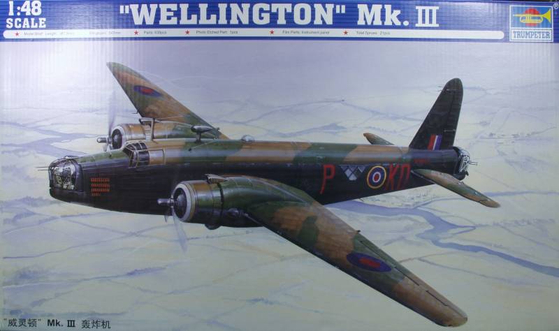
The Trumpeter Wellington comes in a large two part top open box with both the top and bottom made from corrugated cardboard. The top has a nice rendition of the Wellington. Inside the box, which in spite of its size, is quite full containing 13 sprues of injection molded plastic parts in a light gray color. Sprues containing the fuselage halves, the wing halves, the flaps, interior floor and bulkheads and the tail planes and engine cowlings are bagged individually. The three sprues of bombs are in one bag, two sprues with the engine parts and propellers are in one bag and there are two other bags with two sprues each of miscellaneous parts. At one end of the outer box is a small inner box containing two bags with clear parts, a bag with photoetch parts, a bag with cast metal parts and a bag containing the two main gear tires which are rubber or vinyl.
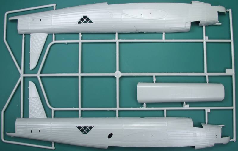
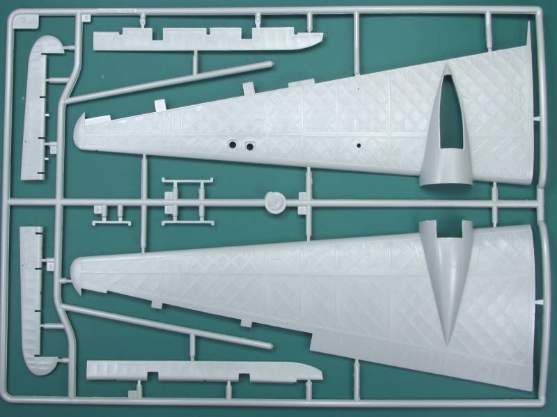
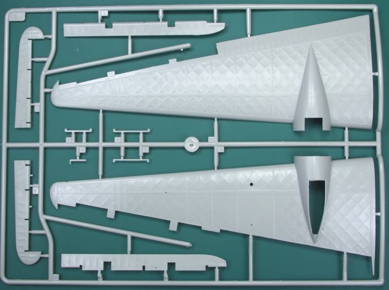
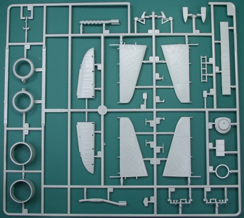
Just looking at the parts one can't help but be impressed, there are a lot of parts in this kit and the initial impressions are quite good. All of the surface metal parts, and there are not a lot of them on the Wellington, feature recessed panel lines and rivet detail. This is basically the engine cowlings, the tip of the vertical stabilizer and the bomb bay doors. The balance of the air frame is fabric covered and it contains both raised and recessed detail as required. The fuselage shows the horizontal stringers under the fabric cover and the wings feature the famous geodetic structure. Most of the controversy surrounding this kit deals with the rendition of these details. I believe many of the nit pickers consider it over done, it is not any more over done than the recessed panel lines on the vast majority of all scale models. Quite honestly, I believe once the surface is painted and given a flat coat it won't look nearly as over done as it does on bare plastic. One could sand it some over all but you would also lose some of the other surface detail. With that out of the way, I'll get off my soapbox and get on with the review.
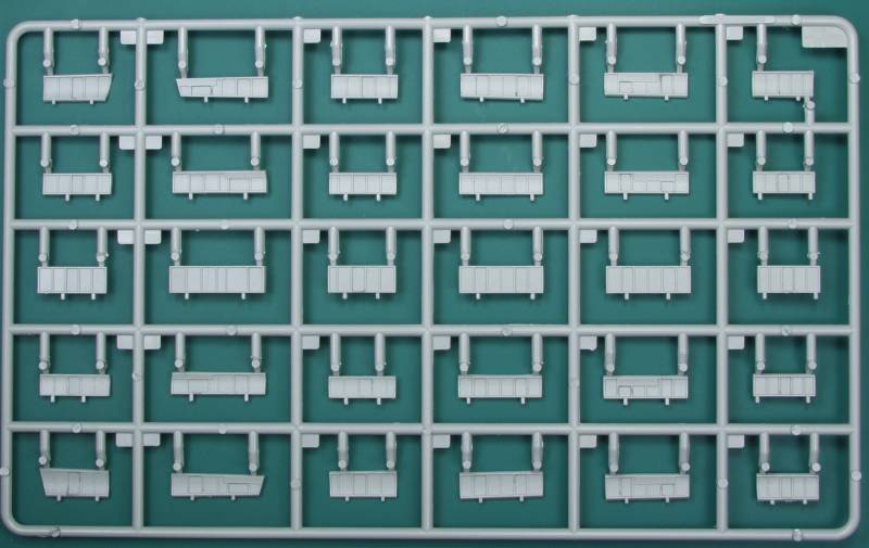
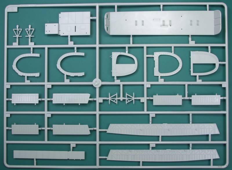
The other fabric detail, such as found on the ailerons and elevators is much more subtly done and looks quite nice. The ailerons and elevators are separate and positionable. The fuselage halves feature the prominent geodetic structure throughout the entire interior. Amazingly there are no ejector pin marks to be found. Some other detail such as panels and electrical boxes are molded in as well. The upper wing halves have wing structure molded in that will show if you drop the flaps but unfortunately there are numerous ejector pin marks there. Ejector pin marks cover the bomb bay side structure as well as the interior floor, there are also some on the back sides of some of the interior bulkheads. While disappointing very few of these will be seen once the fuselage is closed up and the bomb bay will only be seen if you decide to open it which means installing 24 individual bomb bay doors. I think I'll go with the one piece closed cover. Looking over the vast exterior surfaces of the kit I found no surface defects that are detectable but with the geodetic structure, it's difficult to tell to be quite honest.
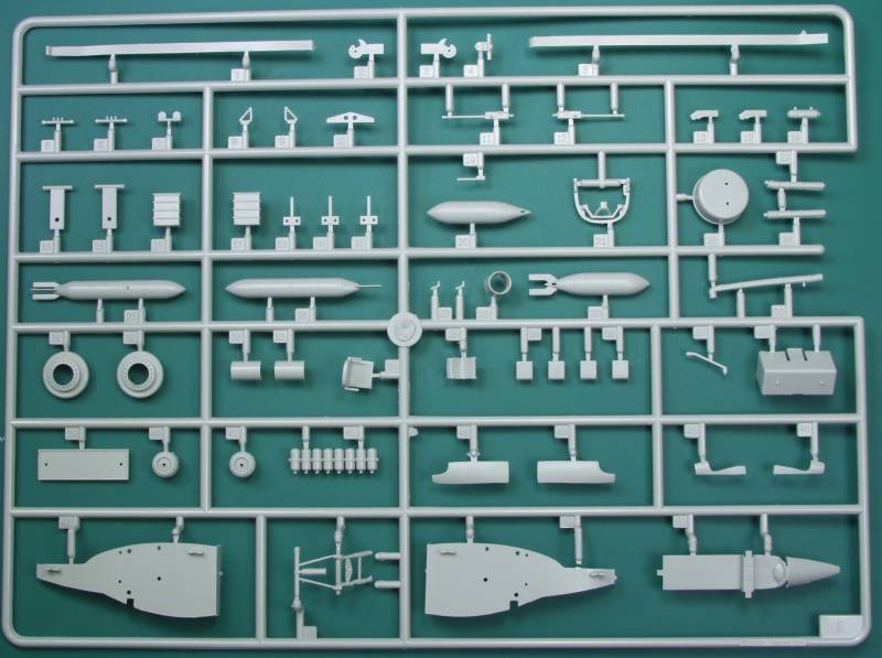
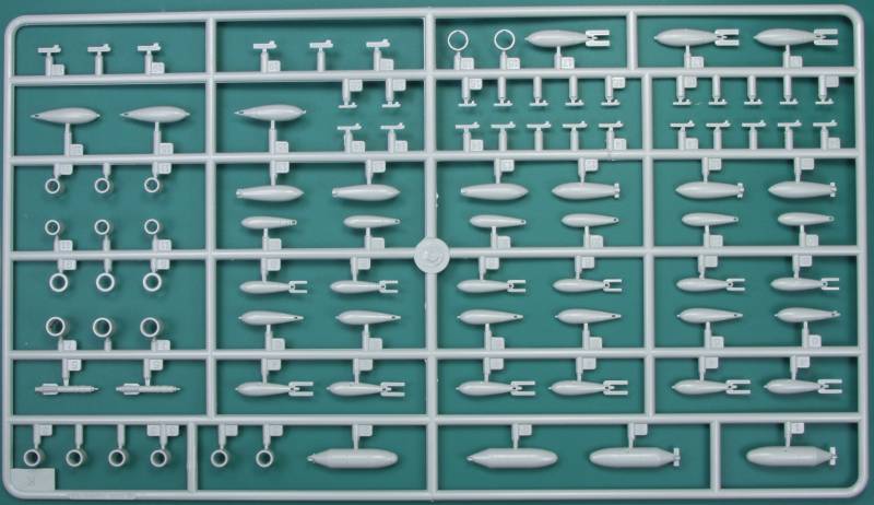
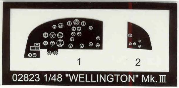
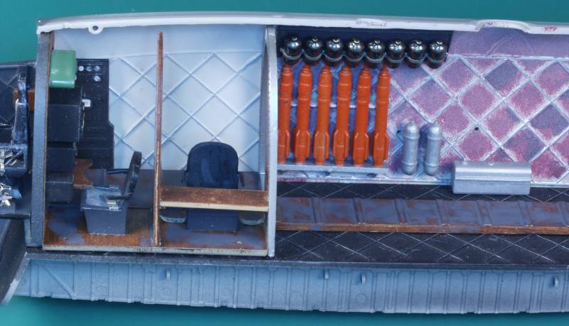
The interior is quite well detailed and complete. There are multiple bulkheads, a radio rack with equipment. The instrument panel is clear with a film to go between it and a backer to provide dials in the instruments. The floor is the roof of the bomb bay and even includes the in flight toilet. The entire interior has a variety of parts that get added to it including oxygen bottles, ammo boxes for the rear turret with feed chutes, the beam guns, a flare chute and other items that are not identified. The kit comes with a bewildering amount of bombs for the bomb bay and there are seven different combinations of loads you can model if you want to deal with installing all of the open bomb bay doors. If you leave them closed you will have quite a load of bombs for your spares box. The turrets have a reasonable amount of detail, enough to make them look believable.
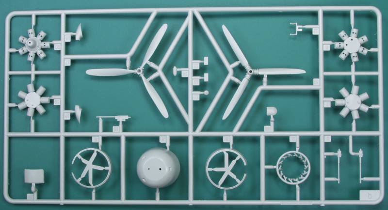
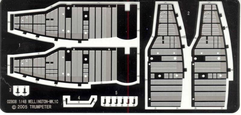
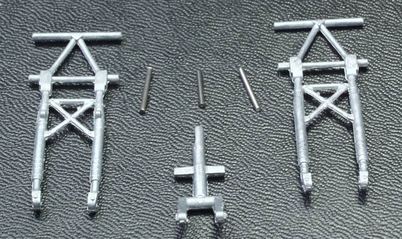
The engines have front and rear cylinder banks and the front bank has the cylinder head to exhaust ring collector pipes as a one piece assembly which is quite nice and beats trying to do individual pipes. There are optional open and closed cowl flaps. The main gear bays are made up with of plastic side walls that get an overlay of very heavy grade photoetch pieces with structural detail etched into them. The main gear parts get trapped between the two side walls then a top piece is installed to close in the well. The main gear is made up from metal parts with a metal shaft that passes through the wheel. The retraction parts are plastic. The wheels, as mentioned earlier, are rubber and are not weighted. The tail wheel is boxed in and the tail wheel strut is also metal with a separate metal pin to mount the tail wheel.
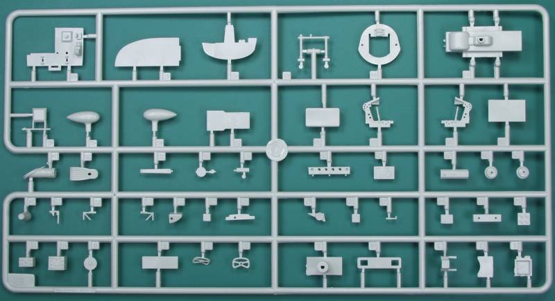
The wings attach with a short box spar that is first glued to the fuselage then it fits into each wing and should make a solid wing to fuselage join. I made no effort to count the parts in this kit the box states that there are 639 pieces in the kit and I assume that includes the photoetch, metal, rubber and clear parts. See photos below. As per usual, duplicate sprues are not shown. See below.
The photoetch parts are used primarily in the gear bays. The areas showing as black are actually very shiny in person but created a reflection when scanned and came out looking black.
The film goes behind the clear instrument panel to provide instrument dials.
The metal parts had a bit of flash on them but shouldn't require much work to clean up and will provide a solid support for this substantial model.
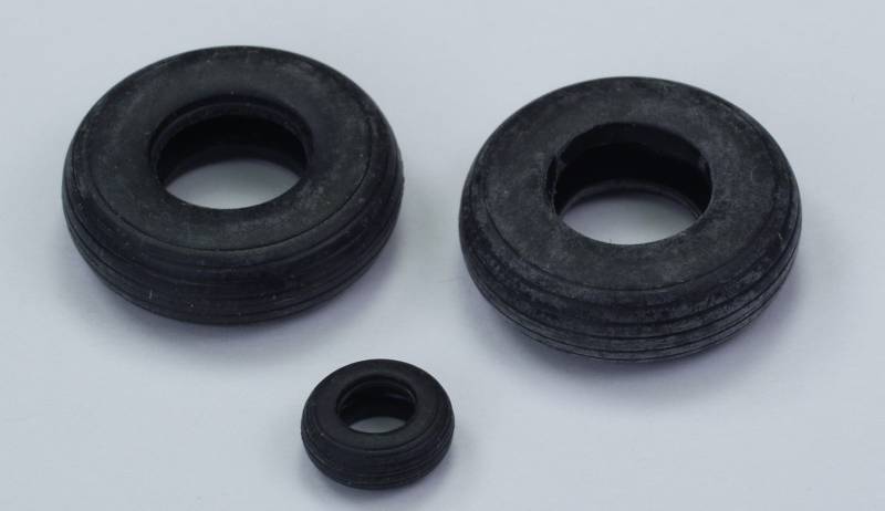
The vinyl or rubber tires. The main gear tires are actually hollow inside, the tail wheel is solid. Due to their bad reputation with the modeling community as a result of issues with the plastisizers in the vinyl reacting to the plastic that they contact, one might consider using after market resin wheels or coating the mounting surfaces with future to prevent actual contact.
The clear parts are very clear and a bit thicker than I'd like to see but have nicely raised frame detail that will make masking easy. The turrets are made such that they have no seams through clear panels. Each sprue was separately bagged and mine came through without a scratch. See below.
![]()
![]()
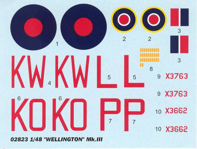
The decals are reasonably well registered and feature markings for two aircraft. The red is criticized for being too red for war time marking but it doesn't look that much different than what is supplied with many other British aircraft. I guess it depends on your personal opinion. The decals look thick enough to be opaque. See below.
The instructions are a twenty page booklet with safety warnings, decal instructions and icon chart on the first page, pages two and three are parts maps and the balance of the pages are assembly diagrams broken down into 36 steps. The instructions are well detailed and thorough and contain painting instructions as they go along. A second sheet approximately 11" x 16" and printed on glossy paper in color contains color profiles of the two aircraft covered on the decal sheet. The aircraft history and specifications are provided on one of the sides of the box top.
After Market Goodies
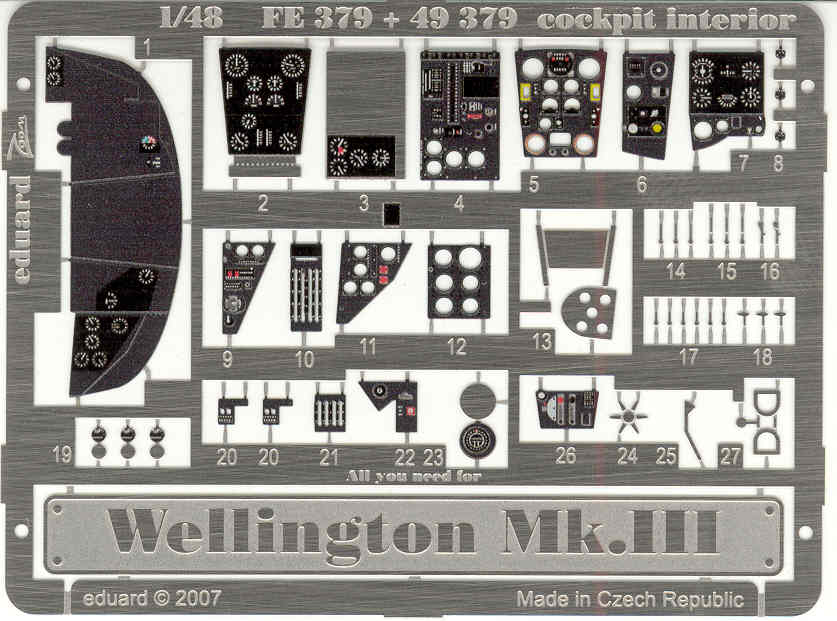
I wasn't all that impressed with the transparent instrument panel so I decided to include the Eduard [FE379] color Zoom set for the cockpit. Eduard also makes sets for the rest of the interior, bomb bay, exterior and dropped flaps if you want to double the price of an already pricey kit, outside of the cockpit most of the interior will not be visible when closed up anyway. See below.
Conclusions
This is a massive kit from the parts count aspect as well as it's physical size. Granted if you close the bomb bay a lot of the parts will not be used. As usual the naysayers are "bah humbugging" the geodetic detail on the outside but this looks like a well engineered kit and I haven't heard of any terrible fit issues so I say build it and let the naysayers vent ! The kit is pricey but I managed to snag mine on sale for less than half price and look forward to building it. Because of the complexity I would not recommend it to beginners but most modelers with a modest amount of experience shouldn't experience any major difficulties. Recommended !
Links to kit build or reviews
A review / build of the very similar Mk IC version can be found here and another in box review can be found here.
References
Famous Bombers of the Second World War by William Green
4+ Publication's Armstrong-Vickers Wellington is an excellent resource of interior photos, diagrams and drawings.
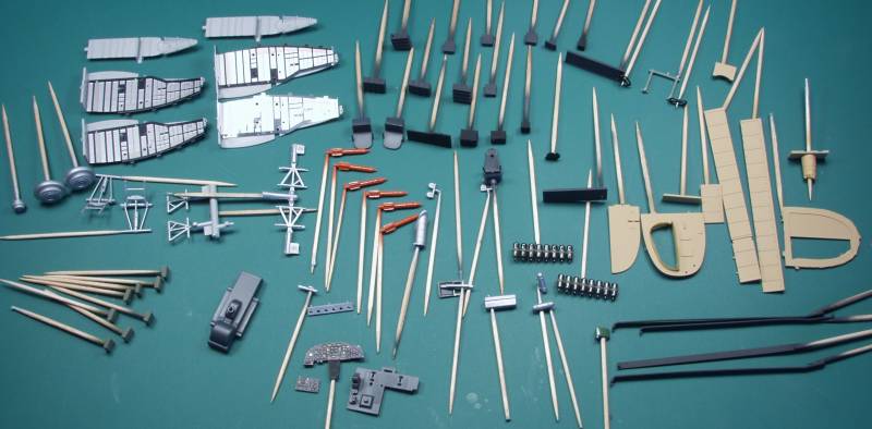
The BuildWhile one might question my sanity in doing the interior of this kit when so little of it will be seen once completed, not doing it would have meant basically throwing away half of the kit so I decided early on to just do it. The second resource listed above was most helpful for determining the look and color of the interior and I highly recommend it.
When I start a kit of this magnitude I like to get as many of the smaller pieces removed from the sprues, cleaned up and painted. The photo below shows most of the interior parts and few of the exterior parts that have been prepared in that way.
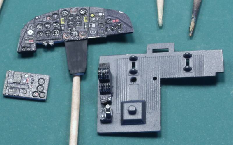
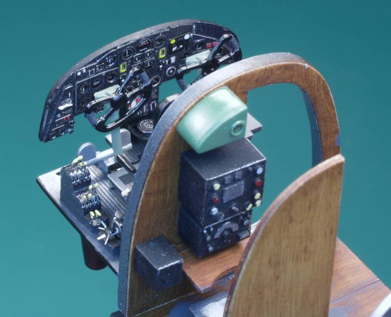
The Eduard PE installed on the instrument panel, floor and bomb aimers panel.
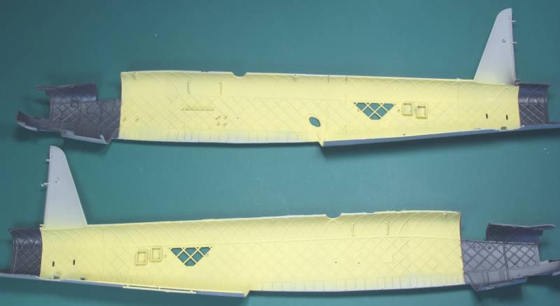
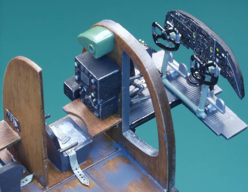
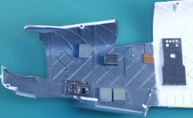
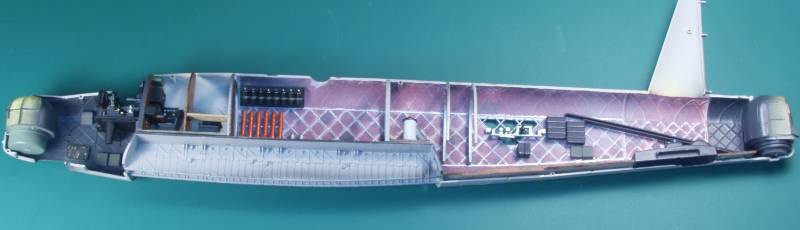
The interior of the fuselage was painted in preparation for the interior, the cockpit area was black and the balance of the interior was painted a linen color as a base for further refinement. The interior of the Wellington was an linen color through which red dope, applied to the outer surfaces, soaked through creating a reddish blotchy pattern.
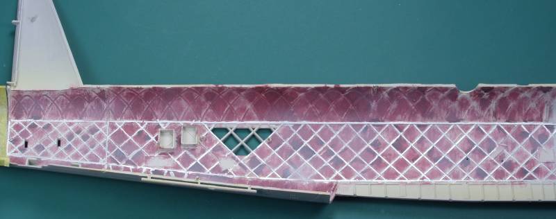
Once the linen color was thoroughly dry I first went over the interior using artists oils, a mixture of red and black to achieve the color I wanted. This was brushed on in a random blotchy pattern and allowed to dry. I then went back over the raised geodesic structure with a prismacolor silver pen. I would have liked to have done it all but the upper areas detail was not sufficiently raised to allow it.
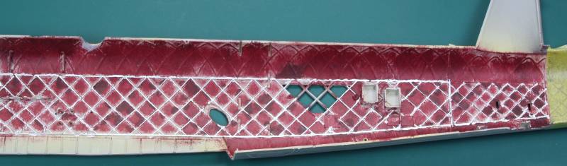
The finished result looked a bit too intense so I gave the whole thing a thin over spray of gray to tone it down. I still wasn't totally satisfied with the result but in the end little of it would be seen.
I then started assembling the interior floor assembly which starts at the cockpit and goes aft. The wood grained effect was done again with artists oils over a light tan base. The wooden parts inside the Wellington looked much like furniture quality. The next six photos show the end results of my labors.
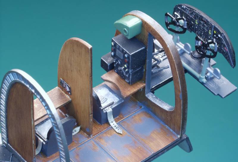
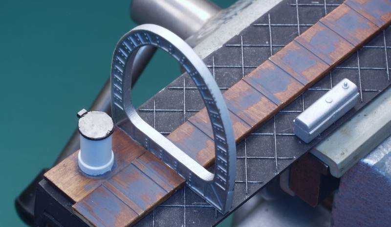
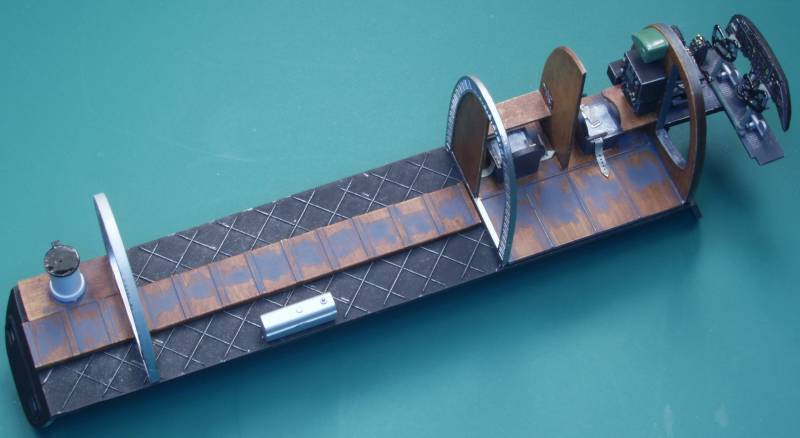
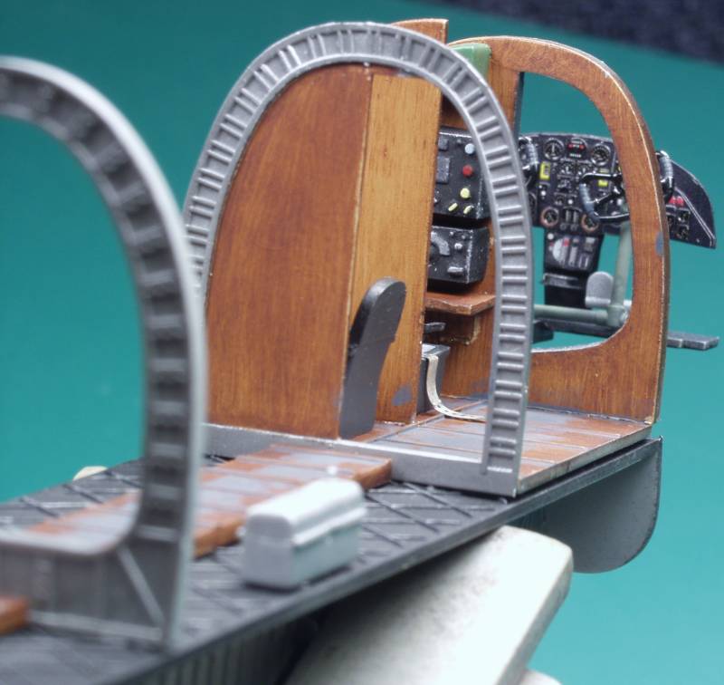
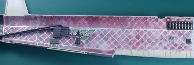
Once that was completed I started adding the detail that mounted to the inside of the fuselage, starting at the front and working aft.
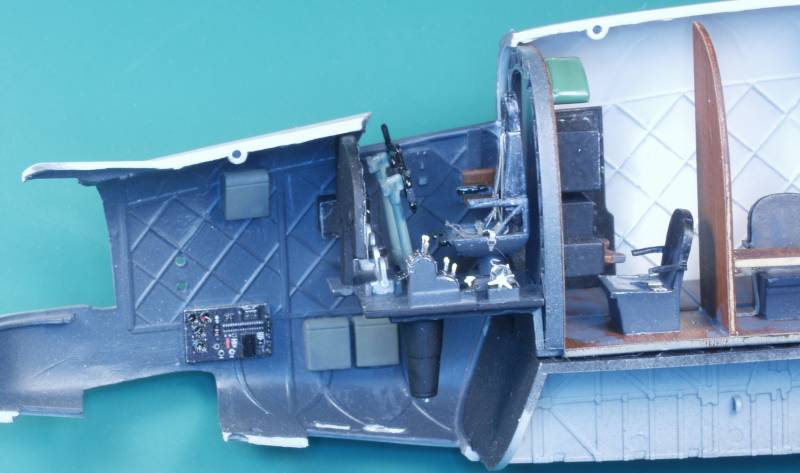
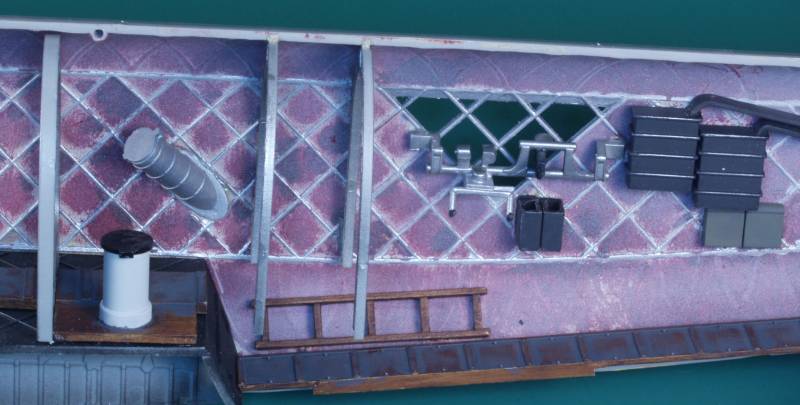
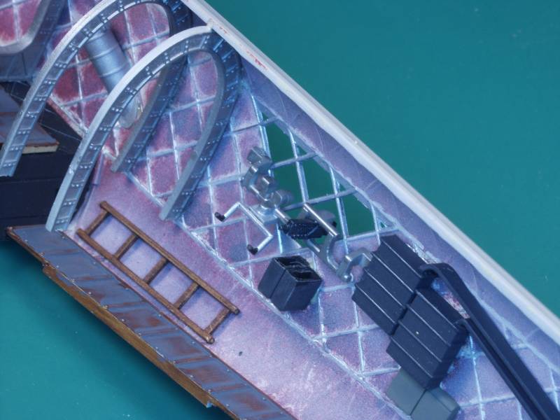
Most of the detail was mounted to the starboard side and only a small amount to the port side.
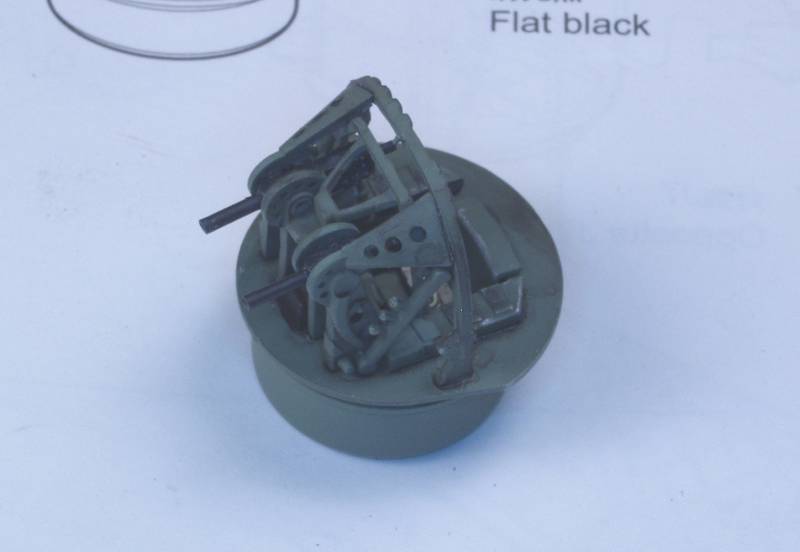
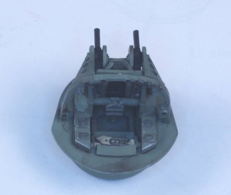
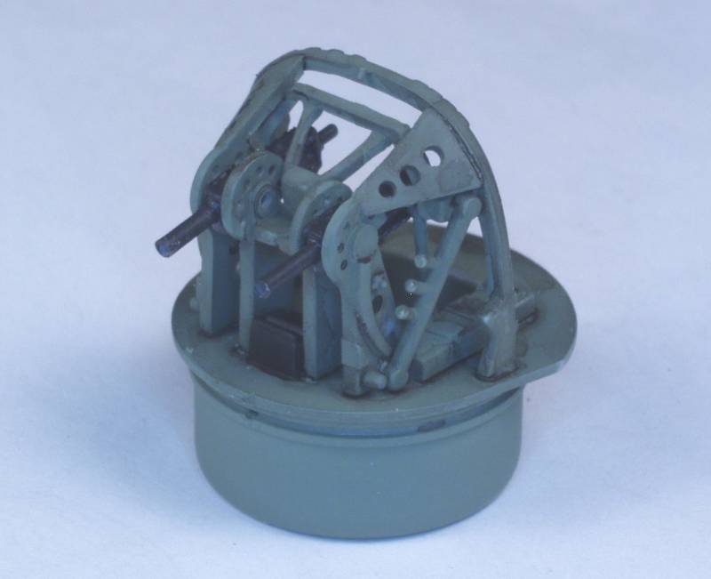
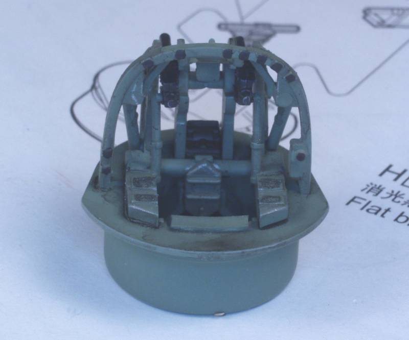
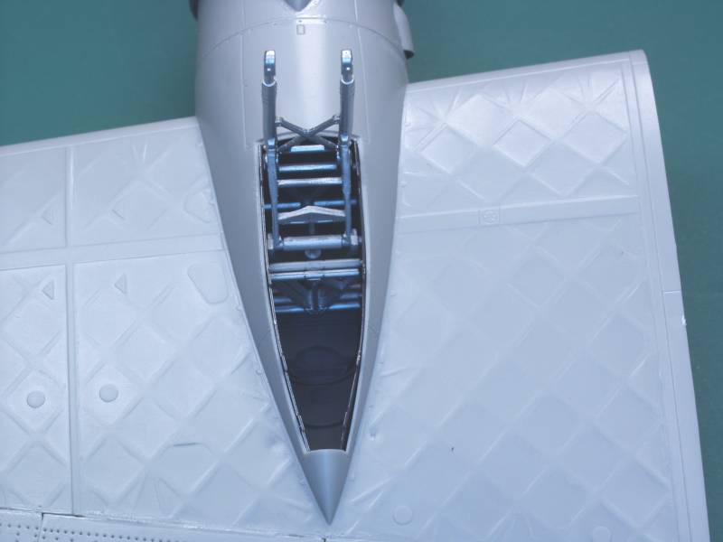
Next up was the forward turret. I cut the kit supplied machine guns off intending to replace them with resin parts much later in the assembly to prevent damage to them. Holes were drilled to receive them. I drill out some additional lightening holes in the assembly as shown in drawings. the front turret went together well and was quite detail, about the only thing missing was some hydraulic lines and electrical cables. The next four photos show the turret prior to install the glazing.
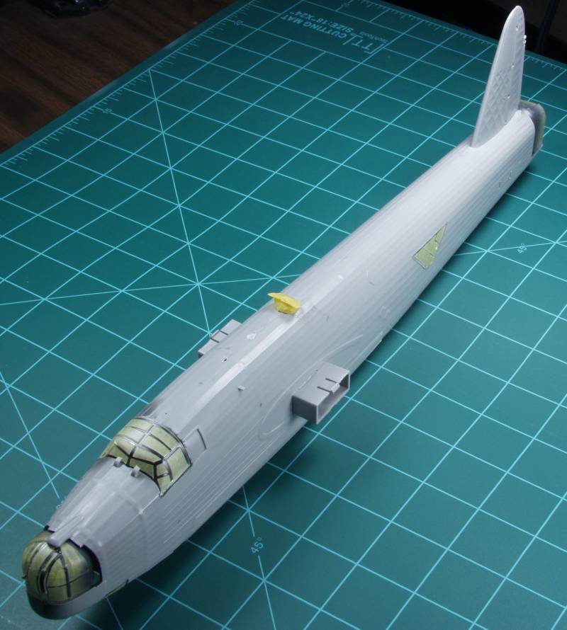
The rear turret was not as well detail and fit together rather poorly. For reasons unknown I did not take any in progress photos of it. The photo below show the fuselage just prior to mating the two halves.
And with one fell stroke, it all disappears. The fuselage fit was pretty good in spite of its size with only a couple spots on the bottom giving me issues.
The gear bays were installed in the wings and the wings assembled.
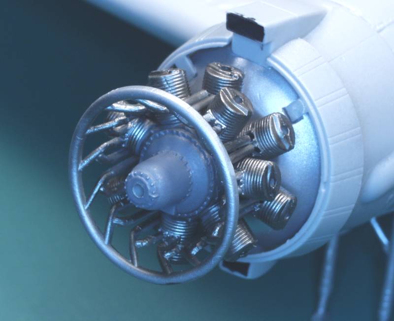
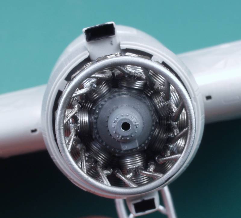
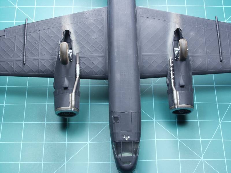
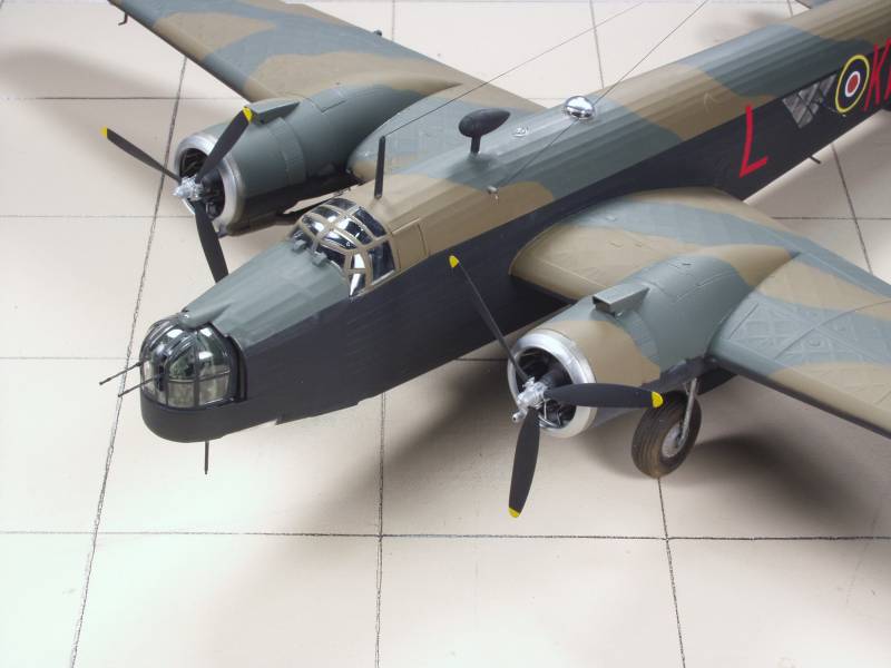
The engines were built up and mounted to the wing. While I'll give Trumpeter credit for doing the exhaust collector pipes trying to align 28 of them at one time just wasn't practical especially when the rear ones really didn't align all that well. Fortunately once together the rear ones really can't be seen so I ended up cutting them off short of their mounting holes. With that done the front ones proved to be an easy fit. I found out later though that I should have shortened the front pipes as well as the collector ring ended up too far forward creating problems mounting the nacelles.
Next shot shows the wings installed. I had some issues with the box spars provided. Two issues, they didn't seem to protrude far enough to allow the latches to lock into the wing and when installed initially and the wing test fitted the wing didn't align all that well with the root on the fuselage. Fortunately the glue hadn't set completely and I was able to pry them back off. By test fitting dry I found the correct position for the spars and by putting a styrene shim under them got the latches to work. I glued them on and very quickly fitted the wing to ensure the alignment was good and made adjustments as required before the glue set. One that was done fit of wings to fuselage was excellent and no filler or sanding required. The tail surfaces were mounted and these also fit quite well.
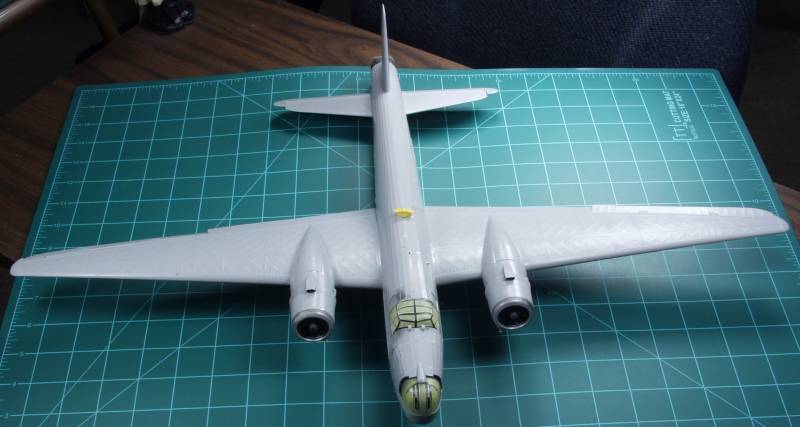
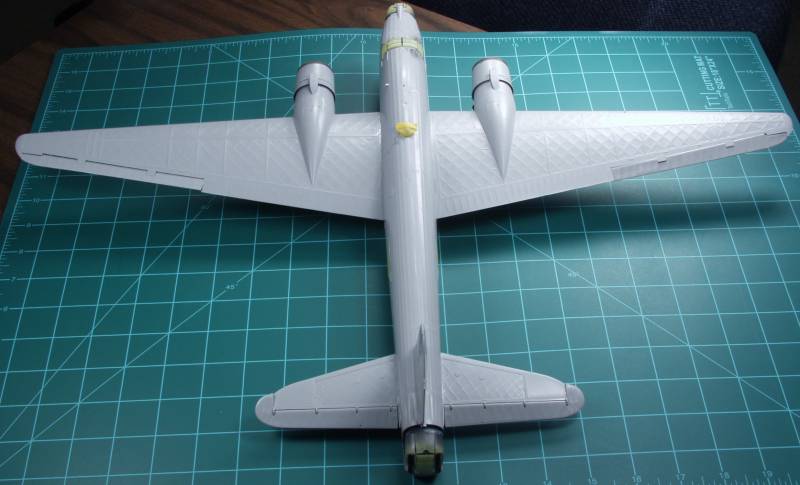
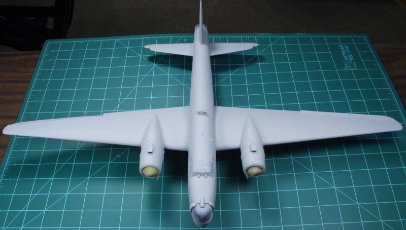
A nice heavy coat of Mr. Surfacer 1000 was applied as a primer and to help fill the slightly exaggerated surface detail.
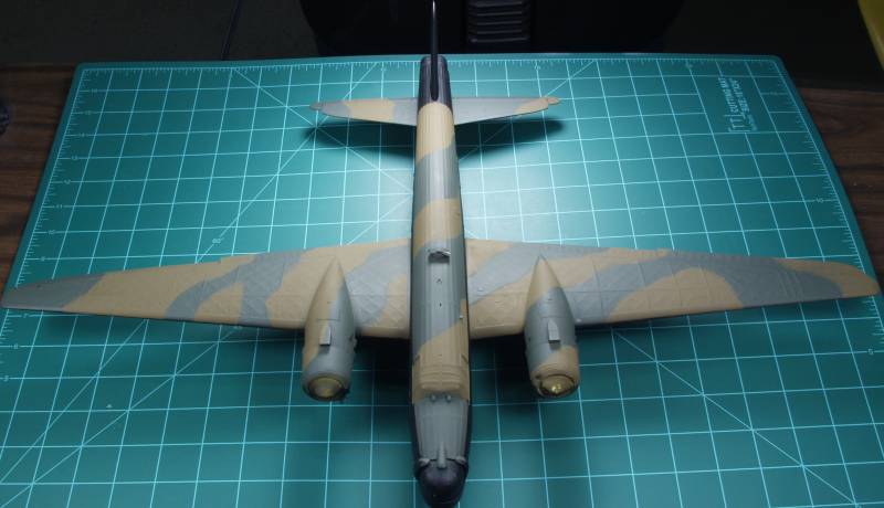
Color was then applied working light to dark making the bottom the last coat which is different than most kits.
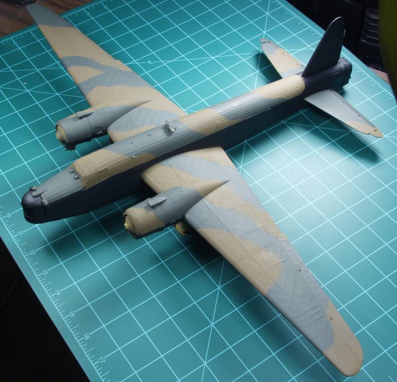
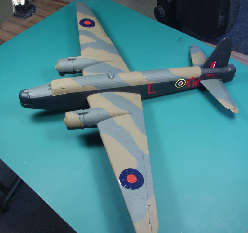
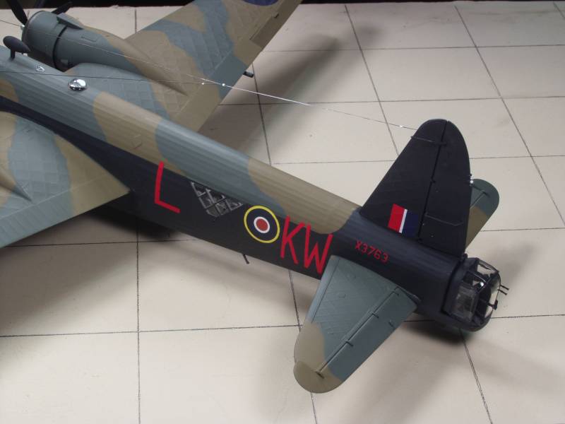
Decals installed. I replaced the roundels with aftermarket decals as the kit supplied items were a bit too red for my tastes. I did not use a gloss coat over all prior to decaling but did buff the areas where decals would go and installed the aircraft number using future. The code letters were relieved of their clear film prior to installation. I did have one letter come apart on me but other than that the kit decals that I used worked OK.
The bottom was given some exhaust staining and the wheels dirtied up and some mud splatters added behind the tail wheel. The three navigation lights on the forward fuselage were replaced with MV products lenses as I thought they looked better than the kit parts as the kit parts did not fit particularly well.
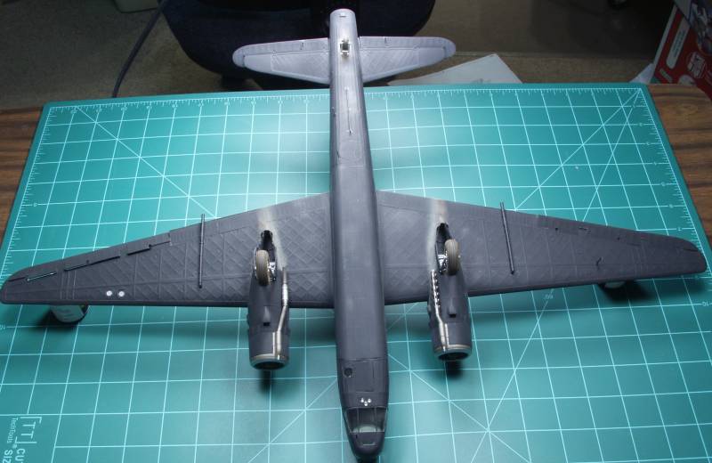
I had a seam issue under the clothes rack antenna on the bottom, the kit part was part of the fuselage making it almost impossible to address the seam, so I cut it off and made my own. I also added the tube for the trailing wire antenna. The kit provided a hole for it but no part.
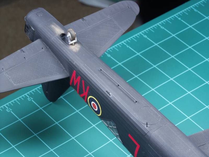
Once the bottom work was done the antenna mast, RDF football and antenna wires were installed

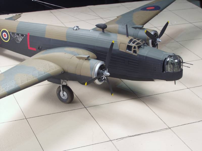
I could have gone more heavily on the weathering but I built the kit as part of a group build and I ran out time.
Overall I found the kit to be a rather enjoyable build in spite of several troublesome fit issues and although I wouldn't do another one with the interior I did enjoy researching and building it.
Back to the Misc British page