
OV-10A Bronco
The North American Rockwell OV-10A was the result of the Department of Defense's Tri Service committee requirement for a Light Armed Reconnaissance Aircraft (LARA) which was formulated near the end of 1963. These requirements were sent out to various aircraft companies of which eleven submitted proposals and from these seven were chosen for closer examination. Of the seven the North American Rockwell was chosen by the Tri Service Committee. Several of the firms bidding protested the selection however only General Dynamics/Convair decided to build a prototype to compete in hopes of winning a "fly-off" competition. Despite this effort; however, the Defense Department did not change its mind and the decision to give the contract to North American was not changed.
The aircraft made its first flight on July 16, 1965, only nine months from contract approval. Following the initial test flight the remaining six prototype aircraft were were delivered up through October 7, 1966. During this period the aircraft were put through a vigorous test program by North American and pilots from all four services. In addition, information from combat reports out of Southeast Asia were factored in resulting in some major changes in the criteria for the OV-10. These included the addition of more communications equipment, self sealing fuel tanks, 300 pounds of armor protection from small arms fire and the ability to operate in a high heat environment. As a result the aircraft could no longer meet the performance specifications resulting in some major changes to the basic design. The most noticeable of these was the increase in wingspan by ten feet and moving the booms out 6 inches. More powerful engines were fitted and that fuselage weapon sponsons were modified from straight to angled downward. Problems with lateral stability in both the original and modified design were solved by the addition of a dorsal fillet at the base of each vertical fin. The various bugs were wrung out by early 1968 an the aircraft was cleared for production under the designation OV-10A
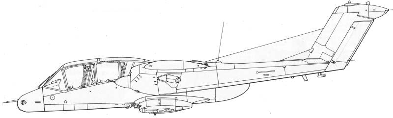
The aircraft's high mounted wing allowed the fuselage and engines to be close to the ground making access to various components easy for ground personnel and provided exceptional visibility for the two man crew. Both crew stations were equipped with a zero-speed, zero altitude ejection seat. Behind the cockpit is a cargo compartment with an area of 110 cubic feet which can carry up to 3,200 pounds of cargo. The cargo compartment floor is at waist level making loading and unloading easy. Besides cargo personnel can also be carried. When rigged for troop carrying either six infantry or five paratroopers can fit in the compartment albeit it's a rather tight fit. The cargo compartment can also be used for additional avionics, communication or electronics gear. It could also be configured to carry ammunition for special mini-gun turrets and their associated gear which have been tested on the OV-10. When the engine nacelles were moved out six inches it helped reduce the noise level and propeller vibration in the cockpit. To eliminate torque the engines turned in opposite directions.
Unlike previous observation aircraft, the OV-10 was designed to carry a wide variety of ordinance on its seven external stores locations. In addition it carried four sponson mounted 7.65mm M60 machine guns with 500 rounds per gun. To supplement this firepower additional gun pods can be carried on the hard points up to the Mk 4 20mm gun pod. Various types of bombs and rocket pods can be carried on the four sponson stations and the fuselage centerline station, up to 500 pounds on the sponsons and 1000 pounds on the center line. The two wing stations are wired to carry and fire the AIM-9 Sidewinder air-to-air missile and can also carry standard rocket pods. The center line station is also plumbed to carry up to a 230 gallon external fuel tank to give the OV-10A extended time over the target or for ferry purposes. This versatility in ordinance capability gave the OV-10A tremendous flexibility and allow the aircraft to be tailored for any number of combat roles, from observation to strike. Combined with its speed, maneuverability, range and short field performance, the OV-10A was ideally suited for the war which was then raging in Vietnam. The first production models began to roll off the Columbus, Ohio assembly line in February of 1968 and within five months, would be taken into combat in Southeast Asia.
I
have my own personal connection to the OV-10. I was employed
at the
North American Rockwell plant in Columbus from May through
December of
1967. During that time I was assigned to the antenna
department and my
connection to the OV-10 consisted of building a production
sample of
the clothes line antenna. The purpose was to verify all
dimensions on
the drawing were correct. I got to go look at the
installation after it
was installed which was a real treat as the OV-10 assembly
line was at
the opposite end of the plant from where I worked. Our
department
was also responsible for drilling the mounting holes in a
Fiberglas
radome that mounted on the top of the fuselage.
The Kit
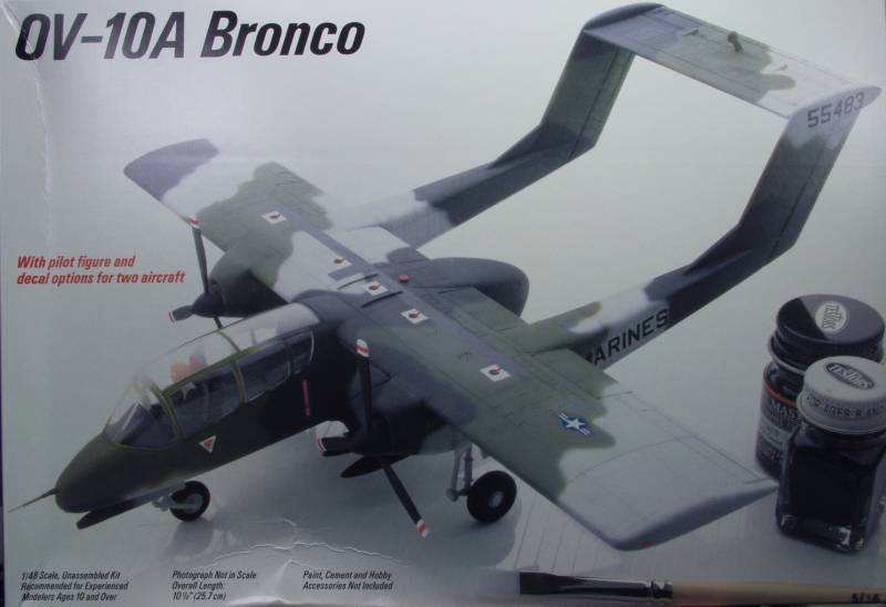
The Testors kit comes in one of those dreaded end flap boxes but at least this one has a slide out tray to contain the parts. On both the top and bottom of the box are photos of the assembled kit which look quite attractive. Inside the box is two bags, one with the main parts and the other with the clear parts. This kit has been around since the early 70's if I remember correctly and in its initial release was based on the first seven prototypes with the short squared off wing and straight sponsons. At some point the kit was updated to include the longer wings and angled sponsons. Unfortunately one thing that didn't change was the spacing of the booms which means that they are 6" too close to the fuselage. I wish I still had the kit I built back then for comparison purposes.
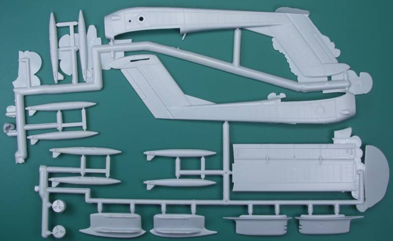
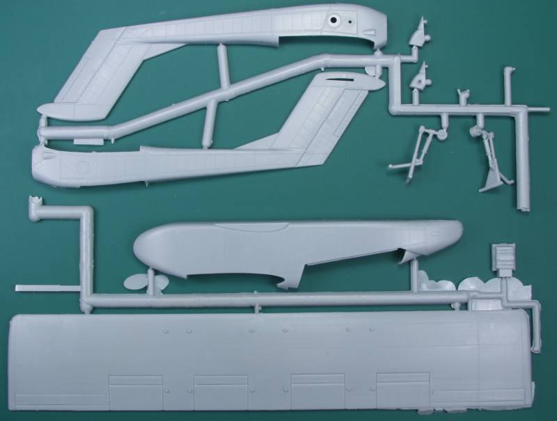
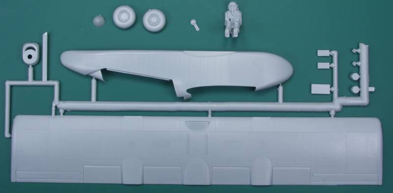
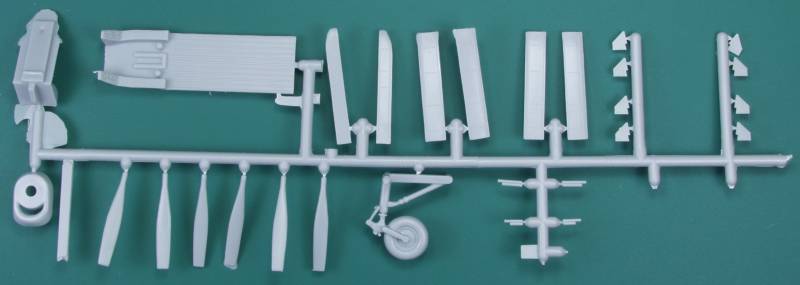
The kit is molded in a medium gray color. Because of it's age the has raised panel lines and rivet detail which is a bit heavy. The kit like many from that time period also had a very simplified cockpit. As can be seen in the photo below some of the parts have quite a bit of flash while others are relatively clean. Whether this is a sign of tool wear or I just got a bad shot I don't know. A number of parts were off of the sprues when I got mine but I bought it from eBay so it may have been suffered from too many shipping's. The molding is pretty good but there are numerous ejector pin marks, many where they will be seen such as the bottom of the horizontal stabilizer, the back of every propeller blade, the pilot seats, the engine exhausts, the bomb fins and the insides of the landing gear doors which also have their part numbers molded on, most annoying ! The fuselage, wing, horizontal stabilizer and the booms are relatively free of imperfections but there is one sink hole on the bottom of each fuselage half. The sponsons all have a sink hole in them opposite of an ejector tower on the back side. The engine exhausts also have a large sink hole in them. The wheels are molded in one piece and are not weighted. The nose wheel is molded integral with the nose gear strut which makes paint that much more difficult. The interior consists of just a floor with side consoles and a pilots seat, nothing for the observers position which is a shame as it will look like a big empty hole through all the cockpit glass. There is a pilot figure included but he looks more the part of a jet jockey and features a large sink hole in his frontal torso. By my count there are 71 parts in gray. See photos below.
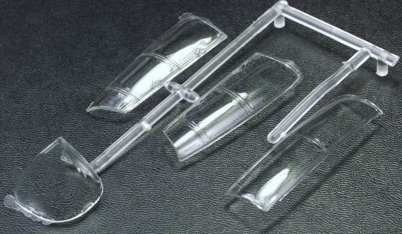
The clear parts are quite clear but rather thick and do feature some distortion. See photo below.
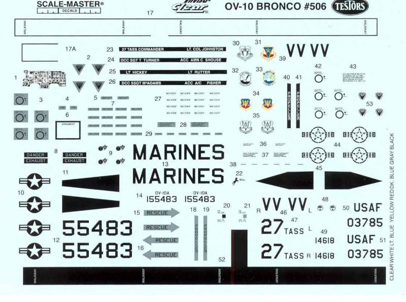
The decals are printed my Scale-Master and appear thin and glossy with a minimum of excess film around them. They include marking for both an Air Force and Marine version. See photo below.
The instructions are in a booklet form, twelve pages long in an 8 1/2" x 12" format. The first page includes a brief history and specifications, and some tips on building, parts prep and painting. Pages two through five are assembly steps. Pages six through nine are painting an marking instructions for the two sets of markings supplied. Page ten has tips on weather and figure painting. Pages eleven and twelve have advertisements for other Testor's products.
After Market Goodies
This kit is a bit long in the tooth having been released decades ago and was originally based on the prototype of the OV-10. Beyond the raised surface detail there were some inaccuracies in the kit, the most noticeable being the twin booms were placed too close to the fuselage. This was correct for the prototype but on production models the booms were moved out 6" on both sides. Since this is the only 1/48 scale kit available currently it is fortunate that Paragon designs has produced an conversion kit that not only fixes the boom issue but provides other pieces that are not included in the kit plus a very detailed cockpit tub to replace the rather barren looking cockpit the kit supplies. They actually make two sets, one for the 'A' model and one for the 'D' model, but as I was out to produce an 'A', that is what I will review here.
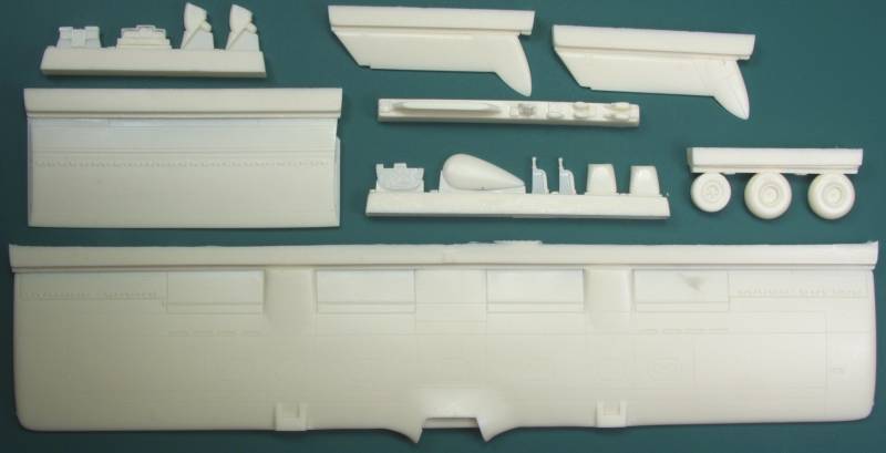
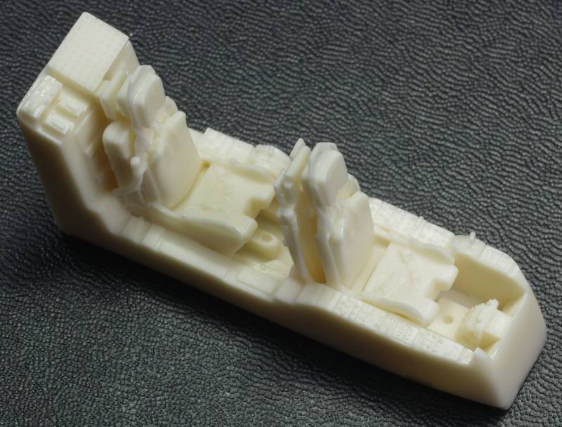
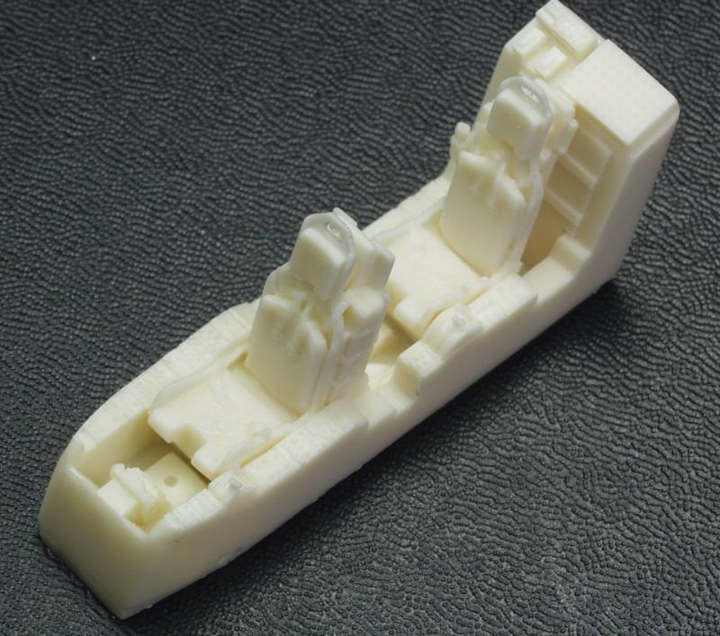
The Paragon Design's conversion kit [48090]comes in a sturdy corrugated box with a flap top box. Inside the box the replacement wing is protected by a piece of bubble wrap. The balance of the parts are in zip lock bags. One has just the replacement cockpit tub, one the photoetch parts and the other the balance of the parts. This is an extensive kit which replaces a good many of the kit parts. The resin parts are molded in a cream color resin. The parts are very nicely molded. The kit consists of a replacement wing with corrected boom positions, a replacement horizontal stabilizer, as with the booms moved out the kit part is now too short, replacement rudders, and a complete cockpit tub which is most excellent. It features both seats already molded in place, side and center consoles. The seats have belts and harnesses molded in. The instrument panel is separate as are dash mount boxes and control sticks. New wheels with weighted tires are supplied. There is a new center line weapon station rack, engine air scoops and exhaust stacks, the upper radome I mentioned in the history section and other external bumps and blisters missing from the original kit. The resin parts are all crisply molded and I found only a few minor bubble holes, one on the wing, and one on one of the exhausts. The wing had a bit of a bow to it which seemed to occur out board of the boom mounting location on both sides. This should be easy enough to correct once the casting block is removed by using hot water.
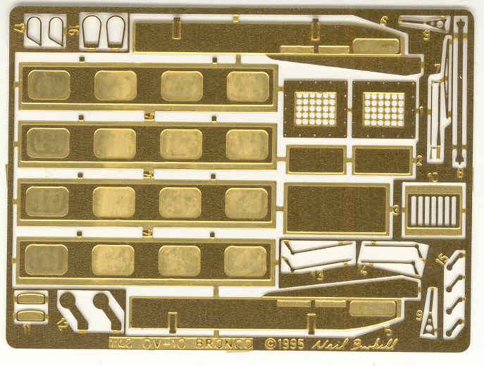
The set also includes a fret of photoetch which includes replacement gear doors with interior detail, mass balances for the elevator and ailerons, vent screens for the booms, ejection seat activation rings for the ejection seats, torque scissors for the main gear, trim tab actuators and a windshield wiper. The instructions are printed on one side of an 8 1/2" x 11" sheet. All the parts are numbered on the casting blocks and fret so make sure you know where they go before cutting them off. While adequate it would be helpful to have some prototype photos to help in getting some of the parts properly located. See photos below.
Conclusions
This
kit is
showing
its age badly and without the help of the Paragon kit
would
require a major scratch building effort to bring it up to
today's
standards. It still will require some effort as to look
right the
raised rivet and panel detail needs to be removed from the
rest of the
kit and new panel lines scribed. The base kit could be
built by
modelers with minimal experience but if you intend to
tackle it with
the Paragon Designs upgrade I would recommend experience
with
multimedia kits before attempting it.
Links to kit build or reviews
Two builds, one with the A series retrofit and one with the D series can be found here and here.
References
OV-10 Bronco in Action by Jim Mesko