G10N Fugaku
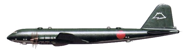
When the tide of the war turned against Japan, it was soon realized that some means to attack the U.S. mainland had to be acquired. It was to be Nakajima who would attempt to provide a strategic long range bomber. The man behind the project was Chikuhei Nakajima, the chairman and engineer of Nakajima. Motivated by his fears over the inability of the Japanese to reach and destroy U.S. industrial capacity, Chikuhei tried to convince the IJN and IJA of the need for a strategic bomber but both services refused to consider his ideas. So without official sanction he invested a portion of Nakajima's resources to draft designs for a bomber that could take off from Japanese bases, cross the Pacific, attack targets on the West Coast of America and either return to their original bases or elsewhere in Japanese or Axis held territory. Nakajima gave the design work the name "Project Z". By April of 1943 Nakajima had assembled drafts and design studies and again presented them to the IJN and IJA.
This time both services took notice but each had their own ideas about the design. By June of 1943 Nakajima had received the input from both services and had begun work on a final design. The design was envisioned to be powered by six of the Nakajima Ha-54, 36 cylinder engines producing some 5,000hp and which was two Ha-44 engines paired together. This engine would not be ready for some time and in fact due to cooling problems at wars end was still only a prototype. Nakajima was forced to settle for the experimental Ha-53 engines of 2,500hp which would have lowered performance estimates. As work progressed on Project Z, plans were made to assemble and house the bombers production line. By the fall of 1943 the plans had been completed and construction of the new facility had begun. By January 1944 the Project Z moniker was dropped and changed to Fugaku which means Mount Fuji.
More pressing demands on Nakajima resulted in less work being done on the Fugaku. To compound the problem, by the time the design was nearing completion, Japan was on the defensive and the chances of producing the Fugaku, let alone using it to attack America were about nil. The fall of Saipan in 1944 sealed the Fugaku's fate. All work was stopped and the plans, calculations and drafts were shelved. Work on the production facility was halted prior to completion and left unfinished. With the Japanese surrender, all documentation was to be destroyed. The papers that survive to this day, including a number of the drafts for various proposals were mislaid or kept for safe keeping by individuals. As a note, although the designation G10N has been used in print for this aircraft for many years, there as been no confirmation in historical sources that confirms this was the case.
The Kit
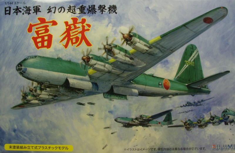
The Fujima kit comes in a fairly large (for the scale) top open tray type box of thin cardboard. The box is almost large enough for a 1/72 kit of the aircraft. Inside the box every sprue is bagged separately in a cellophane bag that is stapled at the top. In my kit a couple of parts had come loose, no doubt a result of the amount of extra space in the box. The parts are molded in a light gray color and feature recessed panel lines only. The panel lines are pretty typical for kits in this scale. My only complaint would be that the lines around the control surfaces are the same size as the panel lines and would look better to my eye if they were deepened a bit. The control surfaces are all molded in the neutral position. I did find a few sink marks on my kit and there was a bit of flash in a few places but not excessive. The kit appears to be based on the version with the 36 cylinder engines but according to my references should have had three blade counter rotating propellers in stead of the four blade versions provided in the kit. However since it was never built it becomes a wiffer and anything goes. Of note, there are apparently more than one boxing of this kit as the one in the review listed at the bottom of this page has different artwork on the box and different decals and a few different parts.
OK,
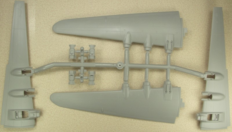
lets look at the sprues. First up is the sprue with the wings. Most
unusual, to me anyway, the wings are attached to a single huge sprue,
one of the largest I've ever seen. Fortunately the attachment points
are located behind the cowlings so it won't be seen. Probably best to
use a razor saw to cut these off. The wings are molded with the wing
tips and trailing edges molded to the upper wing. A method typically
used to allow for sharper trailing edges but in this case the trailing
edges still seem a bit thick to me. It also creates a seam that isn't
a
panel line although in this case part of the seam is along the flap
line. The four other parts on the sprue are the bottom portion of the
four outer cowlings. The wings feature a lot of quite large alignment
pins and alignment ridges that should make for a quite sturdy
assembly.
This is probably a good thing as both the upper and lower wings had a
bit of a bow to them. There are also some minor sink marks on the wing
upper surface where the trailing edge of the wing was molded on the
underside. A bit of a puzzle was a number of what appeared to be
flashed over holes on both the upper and lower wings but none are
called out to be opened up.
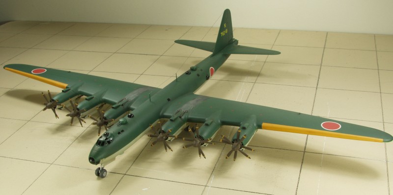
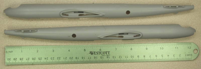
As you can see this is a large kit for 1/144. The fuselage halves were not attached to a sprue. The injection point is on the opposite side. The wing attachment point design appears to be quite sturdy and hopefully will fit well too.
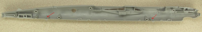
In this photo the injection tangs are pointed out. These will need to be trimmed off before assembly. Like the wing the alignment pins are quite large and hopefully well aligned.
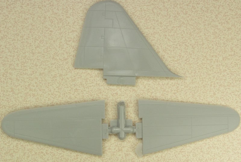
The vertical tail wasn't attached to a sprue and was bagged with the horizontal tail planes. You can see some flash on the tail planes and note that the control surface lines are a bit shallow. They both feature nice sized alignment tabs.
The next sprue has the engine cowlings and propellers and a stand which is actually more of a cradle if you wish to display the model in a flying mode. The parts at the very bottom will be discussed in the next photo. The kit supplies four bladed counter rotating props and six bladed props. According to my reference the counter rotating props were to be three bladed and the single props four bladed but all of this may be speculation since none were every built. The counter rotating props were intended for the 36 cylinder engines which were abandoned during the study and the four blade props were for the smaller substitute engines. The engine cowlings feature only cooling fan detail in the front.
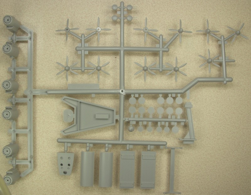
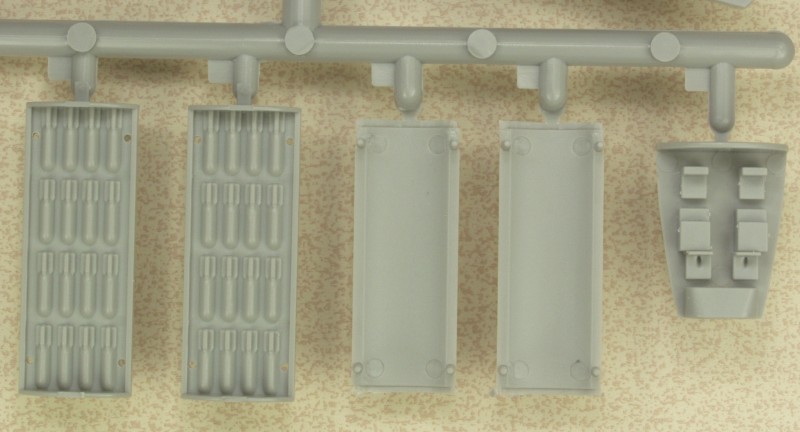
The parts at the bottom of the above photo were orientated in the wrong direction to see them. They are the bomb bay interiors should you want the bay doors open and the bay doors which will need to be cut apart if you want them open. All the way to the right is the extent of the interior detail but little will be seen anyway.
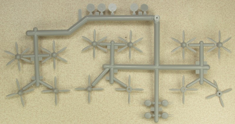
Another sprue with more propeller parts, the round items at the top are propeller shafts which can be installed to make the props turn able. Clear at the bottom are four turrets, two for the top and two four the bottom
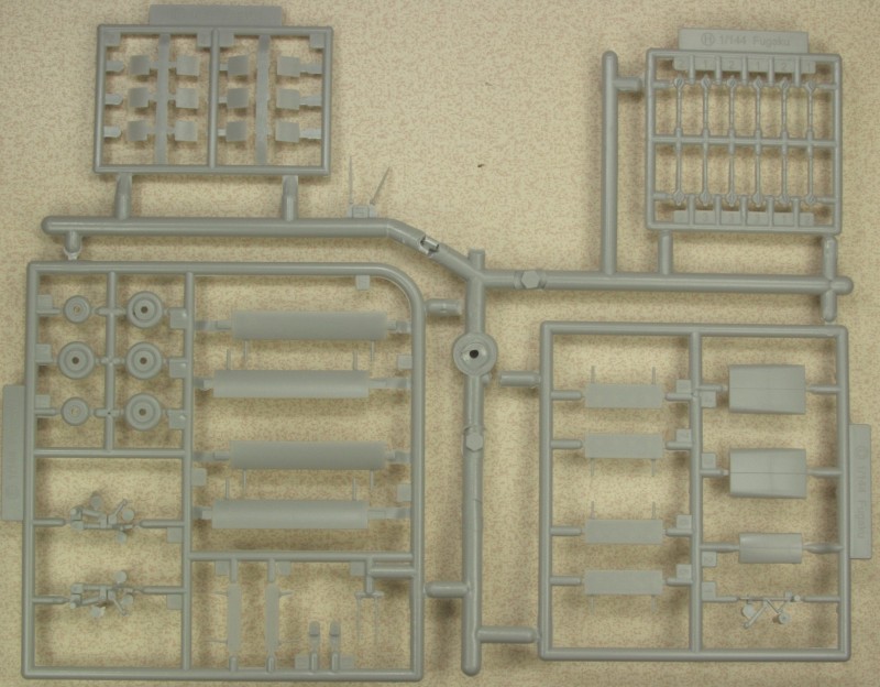
The next sprue contains the balance of the parts. In the upper left the square parts are cooling flaps for the engines which appear to be installable open or closed. Top right are the turbo superchargers, two per engine, which again would indicate the 36 cylinder engines, one super charger per bank of cylinders. The balance of the parts are the landing gear and landing gear doors
The clear parts are rather thick and not all that clear. Hopefully a quick polish and some Future will make them better. Not much to see inside anyway. Since the parts are oriented in different directions I've show the parts from two different angles.
![]()
![]()
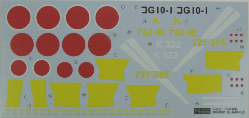
The decals feature markings for four schemes, overall natural metal, green over gray, green and brown over gray and overall green. The decals appear a bit thick but opaque, are semi gloss and they are in register The small red dots are for fueling points.
The instructions are printed on a long sheet, folded to form six panels. The first panel has general instructions and safety warnings in four languages including English and an icon chart, the second panel has a color chart with what I think are Gunze numbers, a parts map and an order form for spare parts, all in Japanese. The next three panels are assembly diagrams which are pretty straight forward which is good cause most of it is in Japanese. The assembly is divided into six steps. the last panel is painting and marking instructions. The kit was intended for Japan and has very little English but the diagrams are pretty self explanatory. No mention was made of the need for nose weight but I'm certain some will be needed.
After Market Goodies
None that I am aware of nor is it likely there will be any.
Conclusions
OK, I'm a sucker for large aircraft and being a Japanese wiffer sealed the deal for me. While I don't have much in 1/144, it is doubtful that it will ever see production in a larger scale. While doing some preliminary test fitting I found that some of the alignment holes were no only undersized for the corresponding alignment pin but that the holes were actually hex shaped instead of round leading me to think the kit might have been intended to be a press fit kit. I also was disappointed in the over all fit of the parts expecting better from Fujima. I can therefore only recommend this kit to more experienced modelers.
Links to kit build or reviews
Another in box review can be found here.
References
Japanese Secret Projects by Edwin M. Dyer, III
Back to the Other Scales page