F7F-3 Tiger Cat
Based on the
earlier Grumman XP-50 that was eventually canceled, the company developed
the XP-65 (Model 51) further for a future "convoy fighter" concept. In
1943, work on the XP-65 was terminated in favor of the design that would
eventually become the F7F. The contract for the prototype XF7F-1 was
signed on 30 June 1941. Grumman's aim was to produce a fighter that
outperformed and outgunned all existing fighter aircraft, and that had an
auxiliary ground attack capability. Armament was heavy: four 20 mm
cannon and four 50 caliber machine guns, as well as underwing and
under-fuselage hardpoints for bombs and torpedoes. Performance met
expectations too; the F7F Tigercat was one of the highest performance
piston-engine fighters, with a top speed well in excess of the U.S. Navy's
single-engine aircraft 71 mph faster than a Grumman F6F
Hellcat at sea level.
All this was
bought at the cost of heavy weight and a high landing speed, but what
caused the aircraft to fail carrier suitability trials was poor
directional stability with only one engine operational, as well as
problems with the tailhook design. The initial production series was,
therefore, used only from land bases by the USMC, as night fighters with
APS-6 radar. At first, they were single-seat F7F-1N aircraft, but after
the 34th production aircraft, a second seat for a radar operator was
added; these aircraft were designated F7F-2N.
The next version produced, the F7F-3, was modified to correct the
issues that caused the aircraft to fail carrier acceptance and this
version was again trialed on the USS Shangri-La.
A wing failure on a heavy landing caused the failure of this carrier
qualification, too. F7F-3 aircraft were produced in day fighter, night
fighter and photo-reconnaissance versions.
Marine Corps night fighter squadron VMF(N)-513 flying F7F-3N Tigercats
saw action in the early stages of the Korean War, flying night
interdiction and fighter missions and shooting down two Polikarpov Po-2
biplanes. This was the only combat use of the aircraft. The F7F-3 was
the most numerous version built with 189 aircraft built.
The
Kit
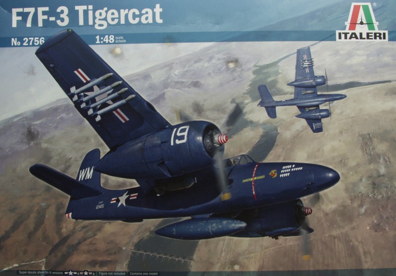
The
Italeri kit is not new, its roots go back to a release by AMT/ERTL
in 1995 and it was released in several different boxings until
1997. In 2007 Italeri pick up the ball and re released it under
their name and again in 2016 with new decals. They didn't bother
to redo the badging on the sprues a they are still embossed with
the ERTL name. The original kit was released about the same time
as their A-20 kit and from a level of detail and quality is very
similar to that kit. Considering its age it still can hold it's
own detail wise. The first release of the kit managed to
stigmatize an entire generation of modelers against the use of
rubber tires on models. What ever compound AMT/ERTL used had the
effect of melting any plastic it touched over a period of time. In
spite of the fact that there have been few if any reports of newer
kits with rubber or vinyl tires causing any issues many modelers
still either avoid them or put a protective layer between the
tires and any plastic parts to which they are attached.
The
kit comes in an average sized top open tray type box of thin
cardboard. The kit parts pretty much fill the box. Inside the box
one finds three sealed plastic bags. One large one with four
sprues, one large one with the fuselage halves and engine
nacelles, two medium sized ones with the wings and tire halves and
one small one with two bombs and the engine cowlings. One medium
sized bag with three medium sized sprues with the balance of the
kit parts. A third bag contains the clear parts. Good news for all
is that the tires are now molded in styrene !
The
parts are molded in a medium gray color and feature mostly
recessed panel lines with recessed fastener detail. The panel
lines are actually quite fine for the time and certainly equal to
or finer than some found on newer kits. There is some raised
detail where applicable. In spite of the age of the kit the molds
appear to have held up well with only a few spots of flash here
and there. Mold separation lines are about average indicating good
mold alignment. The only surface anomalies I found were some very
light sink marks on the outer fuselage in the area where detail is
molded on the inside. This could easily be considered oil canning
if you are not inclined to fill. There are ejector pin marks, the
most annoying in the center of the cockpit side wall detail
although as narrow as the cockpit it they might be difficult to
see. They also exist in the nose gear bay side walls and the main
gear bay side walls. Again they will not be that visible when
assembled.
The
fuselage side walls as well as the gear bay side walls have molded
in detail that should satisfy most modelers. The cockpit is fairly
basic as were many kits at the time this one was released. A
floor, rear bulkhead with separate seat, joy stick and instrument
panel. Seat belts and shoulder harness are supplied as decals as
is the instrument panel. The instrument panel features recessed
instruments with clock details and various raised knobs and dials
which look like they would be challenging to get a decal to fit
over. If you are so talented it would look really nice painted up.
The
engines have completely molded front and rear cylinder banks with
fine fin detail, push rods and separate gear cases and ignition
harness for the front. The propellers are one piece moldings and
nicely done. One in my kit had some molding debris on one blade
that will need to be cleaned up.
The
landing gear are rather complex but nicely molded and feature
molded on brake lines.
The
tires are molded in halves with nice tread detail. The hubs are
separate and nicely molded making paining easier.
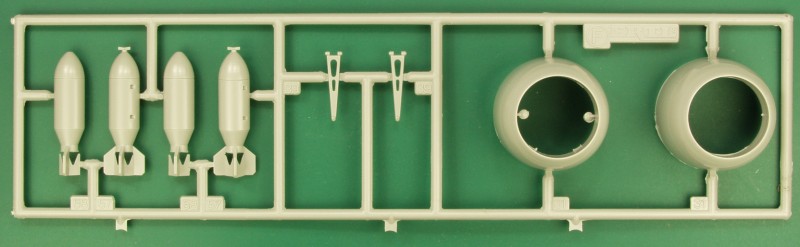
Eight
rockets are provided as are two bombs for underwing stores.
If you intend to either of these the wings need to be drilled out
before assembly. The instructions on show drilling the holes for
rockets. The kit also supplies an center line fuselage drop tank.
The rack for this is molded on one of the fuselage halves. A
boarding step is supplied to attach to the fuselage. The wing
mounted guns are separate parts but the fuselage mounted guns are
just molded into the gun recesses. No mention is made of adding a
fuselage weight to prevent tail sitting but a 55 gallon drum with
a box on top of it is supplied to hold the tail up.
OK,
lets look at the parts...
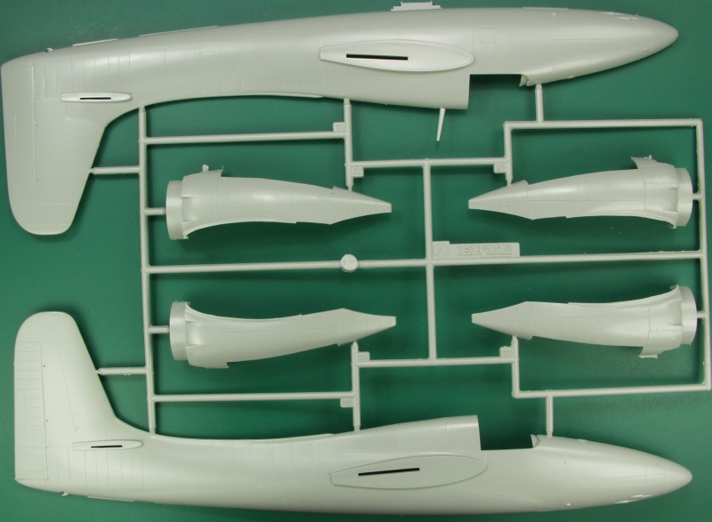
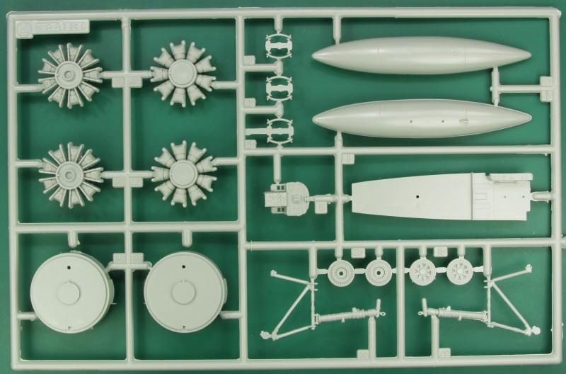
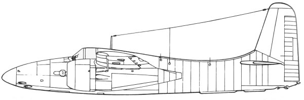
First
up are the fuselage halves and nacelle halves. The top antenna is
molded to one half, never a good practice in my opinion and on
mine it didn't survive the review process.
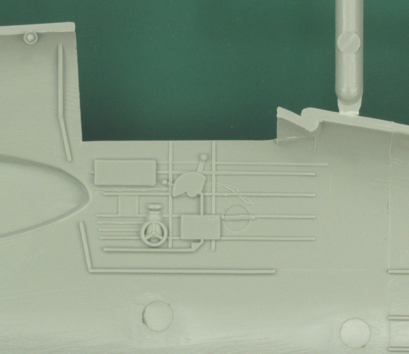
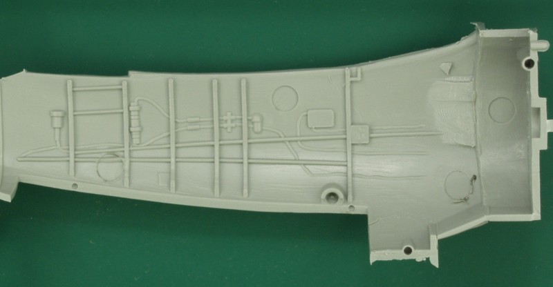
The
next two photos show the molded on detail in the fuselage and nacelles.
Note the prominent ejector pin marks.
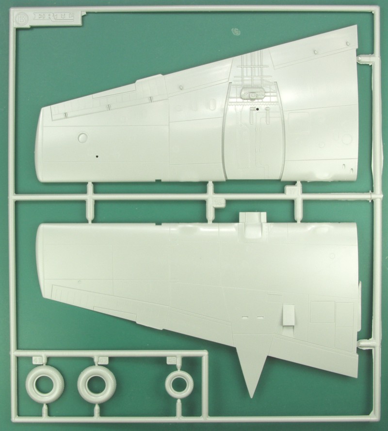
Wings
and tires next, there are two of these sprues.
The
next small sprue has the bombs, two gear strut parts and the cowlings.
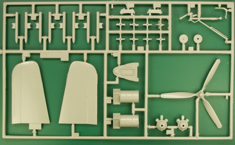
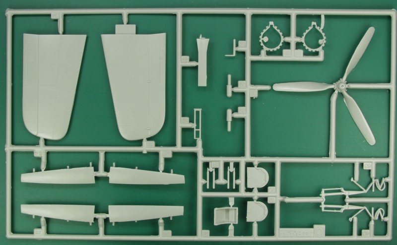
The
next two sprues both have the horizontal stabilizers and props but the
balance of them feature a variety of parts.
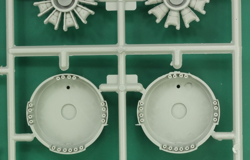
Engines,
drop tank, bomb stabilizers, cockpit floor, instrument panel, drop tank,
gear struts, wheel hubs and forward nacelle/engine mount parts.
Photo
shows the back side of the forward nacelle parts with the engine exhaust
stubs. These would benefit from being drilled out a bit.
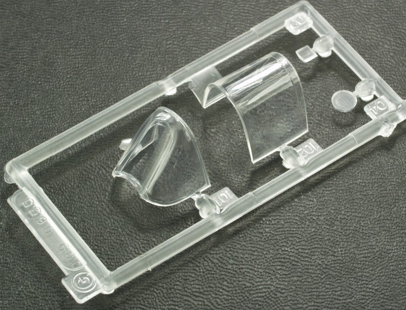
The
clear
parts are reasonably thin and clear but does have some optical
distortion.
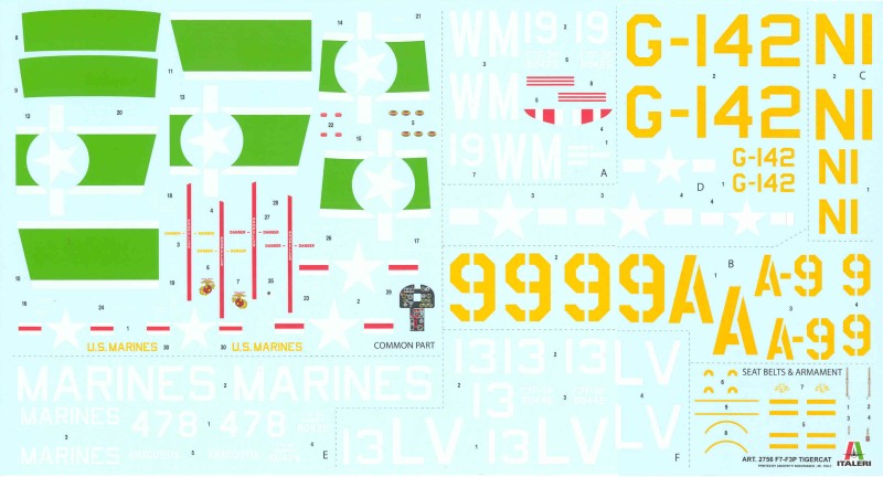
The
decal sheet is huge nearly filling the bottom of the box and
contains markings for 6 aircraft, all in overall blue. The sheet
is nicely printed, in register, glossy and at least on the sheet
appear opaque. This is sometimes hard to determine on white and
light colors. Excess film has been kept to a minimum where
possible although the large combined numbers and letters would
probably be better cut out and applied separately. The sheet is
printed by Zanchetti Buccinasco or so it says on the sheet. A
new name to me. Markings are for the following aircraft:
U.S.M.C., MAG-33, Phoang, Korea, 1953;
U.S.M.C., MAG-33, VMF-312, MCAS El Toro,
California, 1946: U.S.M.C., VMD, Oakland, California, 1946;
Naval Air Station Livermore, California, 1946; Naval Air Station
Anacostia, Washington DC, 1950; U.S.M.C., VMP-354, MCAS Cherry
Point, North Carolina, 1949. A note concerning the markings, the
first one listed and the last two listed are F7F-3P photo
reconnaissance aircraft and the kit does not have the camera
doors which were located on the lower portion of the aft
fuselage.
The
instructions are in a tall narrow format booklet
stapled at the spine 14 pages long. Page 1 has a
brief history in six languages and the usual
safety warnings also in six languages. Page 2
and 2/3's of page 3 are a parts map and also
includes a color chart. The color chart has
generic color names, FS numbers and an Italeri
Acrylic paint numbers. The bottom 1/3 of page 3
starts the assembly drawings which continues
through page 7 in 8 steps. assembly drawings are
clear and have color call outs. The balance of the
pages except the last page feature the paint and
marking schemes. The back page is an order form
for replacement parts.
After
Market
Goodies
Due to the age of this kit there have been
lots of aftermarket produced although much of it is long out of
production. A good place to look to see what all has been
available is Scalemates,
here is a link
to the F7F items.
Conclusions
This
kit reminds me a lot of the AMT/ERTL A-20 kits, done at about
the same time. It's a relatively simple kit, nicely detailed and
most reports indicate it assembles reasonably well. The most
challenging part will be finding room for enough weight to keep
it from being a tail sitter. For now it's the best (and only
one) in this scale.
Links
to kit build or reviews
I
have only found one other in box review here
and no build reviews. Reviews for the original AMT/ERTL kits
abound, Google is your friend.
References
Wikipedia and F7F Tigercat in action by
Captain W.E. Scarborough
Back to the Miscellaneous U.S.
Page
Updated 2/12/19