
Ta 154
The Ta 154 is yet another example of a Luftwaffe could have been. In 1943, with bomber production declining there was a surplus of Jumo 211 power plants available and the RLM was receptive to the idea of building a fast attack aircraft utilizing these engines. They were also much impressed by the British Mosquito. The RLM gave Kurt Tank, director of Focke-Wulf, the assignment of designing the aircraft with three conditions: the twin engined plane was to be made of wood, use the Jumo 211 and production was to start quickly.
The RLM later decided, based on the current war situation that it would be more advantageous to build the new aircraft as a night fighter. Focke-Wulf was chosen to produce the new fighter for two reasons. First, unlike Junkers, Messerschmitt and Dornier, it had no adaptable twin engine designs and the RLM felt that the company would readily accept the challenge of a completely new development program and second and more importantly the reputation of its director Kurt Tank, who was held in such high esteem that he was alloted design numbers using the first two letters of his surname, hence the "Ta" designation. The officially suggested name for the plane was to be the Wasp (Wespe) but from the outset the plane was known as the Moskito in ironic recognition of its general similarity to the British Mosquito. The design was original with the aim of producing a night fighter that would be superior to the Mosquito and the British influence was slight. Anticipated shortages of light metals were not the only reason for the Ta 154 out of wood. Hermann Goring considered it imperative that the Luftwaffe have its own "wooden wonder". He felt that the English plane that roamed with impunity over the Continent represented a challenge that the German aircraft industry could not ignore and anticipated great psychological and propaganda benefits from beating the British at their own game.
The prototype was completed in less than 10 months from the date of the RLM requirement. The plane had good flight characteristics but was plagued with hydraulic problems. The prototype which lacked radar, armament and flame dampers is credited with having a top speed of 435 mph however the complete set of flight reports for the prototype covering 181 flights reveal the that a top speed of 389 mph at 20,500 feet was attained during speed trials in 1943. Typical of many of the aircraft design programs of the time a large number of prototypes were built, fourteen in this case, each attempting to fulfill some new RLM requirement. Beginning in March of 44 the first of 22 preproduction fighters were completed. Hydraulic problems continued to plague the program and numerous accidents and plane losses resulted. The RLM issued an order for 250 night fighters in the Fall of 43, however there existed in the German high command a strong antipathy towards all specialized night fighting aircraft. They felt that outmoded and converted day types such as the Bf 110, Ju 88 and Do 217 were adequate. Even the superior He 219, which was further along in its development was finding particular resistance from the RLM to its adoption. It was an open secret that Erhard Milch favored the Ju 388J, despite its drawbacks but even this type never entered service. The reason for this official antipathy was Hitler's refusal to think in defensive terms.
It was only the alternative role of the Ta 154 as a counter to the De Havilland Mosquito that led to its being given a production order at all. The dual missions of Mosquito chaser and night fighter would haunt the fighter throughout its career, eventually being responsible for its failure to see widespread operation service. Early in 44 an informal comparison flight was made with the He 219. The test pilots from their respective companies swapped planes. The Heinkel test pilot noted that the Ta 154 had much better acceleration and was more maneuverable than the larger He 219 but was less stable around all three axes and though it lacked the excellent visibility of the 219 it was far more responsive to control inputs and offered sufficient visibility for night operations. The Focke-Wulf pilot noted that the Heinkel fighter that was heavily armed and armored weighing half again as much as the 154 but with about the same horsepower was sluggish and just barely able to get around the pattern on one engine and lacked the acceleration of the 154. The top speed of the 154 was higher but it had a shorter endurance and range than the 219. Both men agreed the the 219 was better suited for operations infiltrating and following the bomber stream whereas the 154 would be better employed patrolling a local area and being vectored by ground based controllers
In June of 44 a Ta 154 crashed when is wing apparently disintegrated. Production was halted and it was found that the glue was at fault. For both political and technical reasons the Ta 154 program was officially canceled on August 14, 1944. The Emergency fighter program of November 44 dispelled any last hopes Kurt tank might have had that any of these developments might be built but technological advancements, particularly with jet aircraft, had left the Ta 154 behind. There can only be conjecture as to the true worth of the 154 since none of them were evaluated in post war test flights.
The Kit
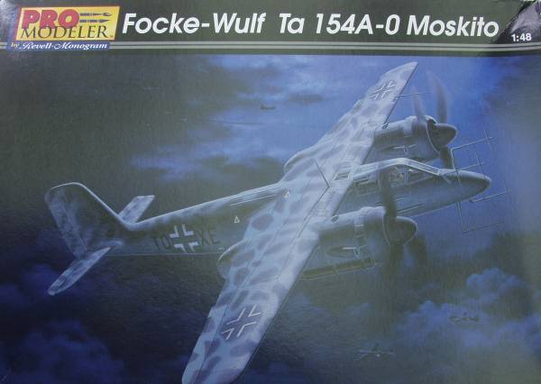
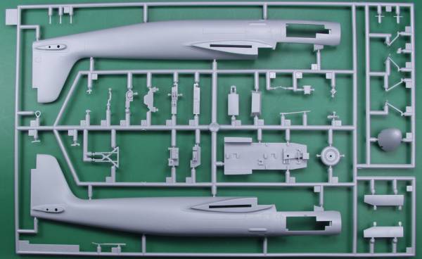
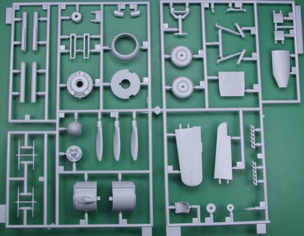
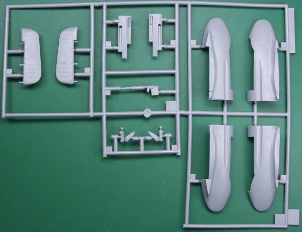
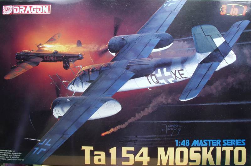
The Promodeler kit comes in a fairly large hinge top box. Not as handy as a two part box but certainly better than an end flap box. It has a rather nice rendition of the 154 in flight. Inside the box was one large bag with five smaller bags inside. Each bag has one sprue except one bag that had two identical sprues. The kit is molded in a light gray plastic with a matte finish and has recessed panel lines and rivet and fastener detail. Since the prototype was made from large sections of molded plywood there aren't a lot of panel lines. The panel lines are fine and consistent. Looking at the major airframe pieces I found no sink holes or other surface defects and the pieces are all virtually flash free. There are some pesky ejector pin marks that show up on the inside of gear doors, inside the cockpit area and the top of the nose wheel bay. Others show up on some of the smaller parts but weren't quite as noticeable. The fabric surfaces are very nicely rendered.
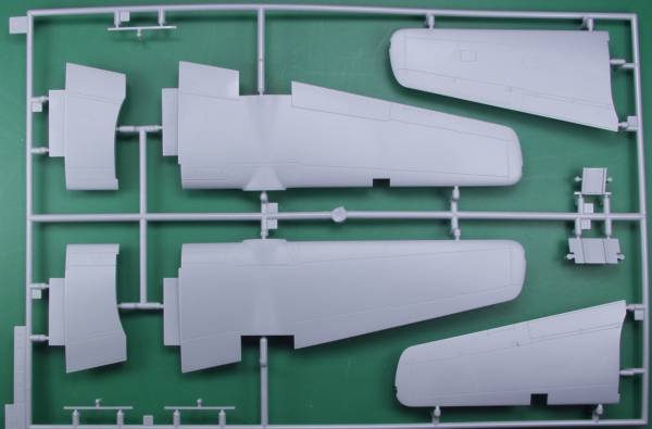
The fuselage has some interior detail molded in and for the most part the pilots area is pretty well detailed, well enough to satisfy many I suspect. The radar operators pit is a little less detailed. All of the flight surfaces except the rudder are molded in place and to position the rudder any way except straight will require removing the mounting lugs. This kit was originally designed by Dragon and it was first released by Promodeler. As a result it has some of the typical Dragon fit issues. One problem that plagued most of the first release of this kit and maybe others as well was a warp in the wings that leads to the wings having a pronounced droop. Most build reviews mention it and a couple give possible solutions so be sure to check out the other reviews listed near the end of this review. Apparently this was caused by not allowing the plastic to cool enough before removing it from the mold. There are also some other fit areas but not as serious as the wing issue.
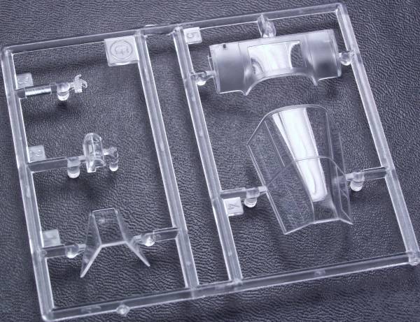
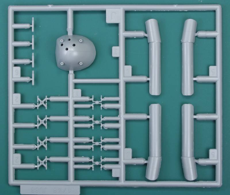
The kit as it comes represents the A-0 series of which there were 22 built. This aircraft had a long and protracted development period and many changes were fitted on the fly or updated later so if modeling a specific aircraft it's best to have photo's or other references as a given aircraft may have changed over time. Dragon has since released an updated kit that I believe has parts to build more versions, has some photoetch parts and it's also more expensive. Altogether there are 133 gray parts, a respectable number for a rather small aircraft. The clear parts are thin and clear with the radar operators glazing molded as part of the leading edge of the wing. The wind screen is molded separately so the canopy can be displayed open or closed. Bagged separately to prevent scuffing mine none the less had what appeared to be as scratch or molding defect in the wind screen and radar operators window. All of the sprues except for one duplicate are shown below.
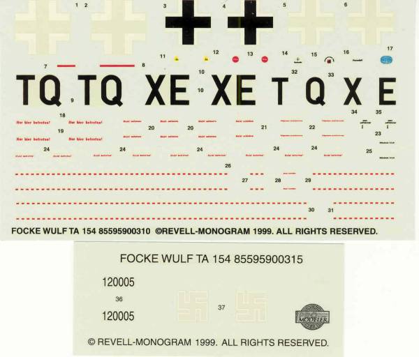
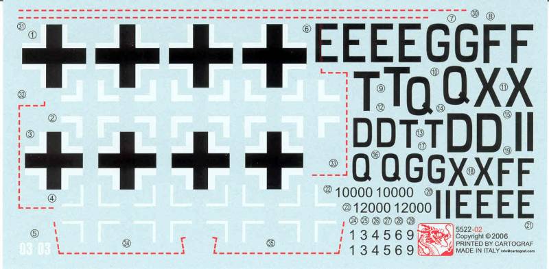
The decals are for one aircraft only but include a lot of stencils. The main sheet has most of the decals on it then in what looks like an after thought there is a second small sheet with the Promodeler logo that includes the tail number and two swastikas. The decals look thin and registered. See below.
After Market Goodies
While the
kit is fairly well detailed out of the box I decided to add to it to
take it to the next level. If you check out the links listed below you
will find that there were a lot of after market products available at
one time for this kit. The ones I chose are listed and reviewed below.
CMK interior resin detail set (4065)
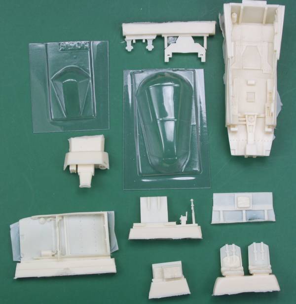
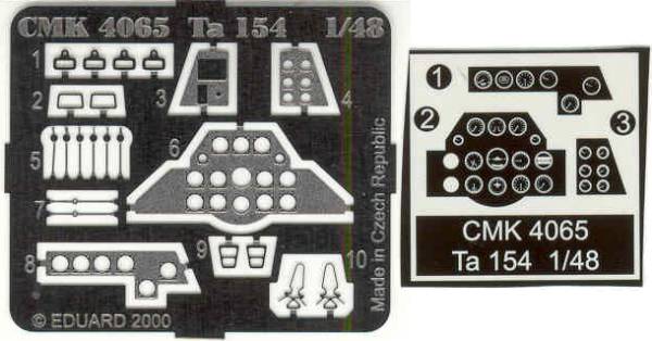
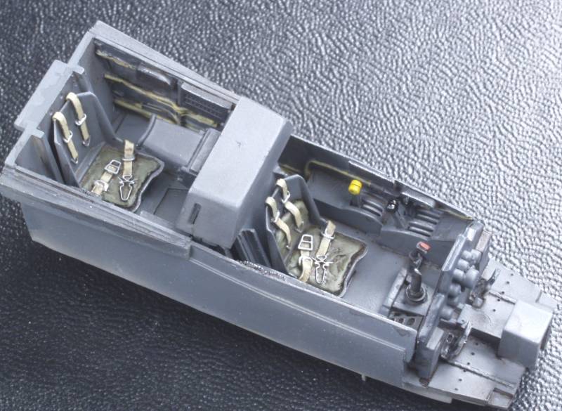
This set consists of resin, vacuformed and photoetch parts. The resin parts are molded in tan resin and consists of 13 parts including a cockpit tub, upper nose wheel well, pilot and radar operator seats with molded in harnesses and belts, a bulkhead that fits between the two crew members, gun sight, stick, rudder pedals, control panel, radar operators panel and radios, and a rear bulkhead. The photoetch parts include buckles for the molded on seat belts, throttle and mixture levers, straps for the rudder pedals and pilots and radar operators instrument panels. A film with instruments is provided for use behind the panels. The two vacuformed parts are the windscreen and canopy. The resin parts are all crispy molded. the cockpit tub has side wall detail molded in and it is all very well done. The side walls are very thin in some places and on mine one was bowed in some. One will need to exercise some care in sanding off the bottom of the tub in order to mount the top of the wheel well. I found only one pinhole in the sidewall of the tub and no short shots on any of the pieces. The photoetch should enhance the pit even more. The vacuformed parts are thin but the frame lines are not particularly well defined so I'm not sure they represent a big improvement over the kit parts. See below for photo's of the contents of the kit.
The instructions which are printed on a 6" x 7" sheet printed on both sides includes a parts map, pictorial drawings of how the parts go together and a color chart that calls out the colors by name or RLM number and has color numbers for Aeromaster and Humbrol. Verlinden also made a set for the 154 but I have not seen it, so I can not compare the two. This kit will certainly raise the level of detail of the cockpit well above the kit level.
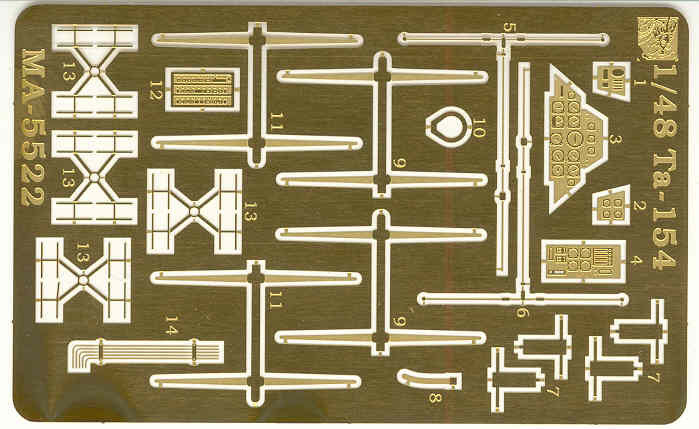
Eduard photoetch detail set (48300)
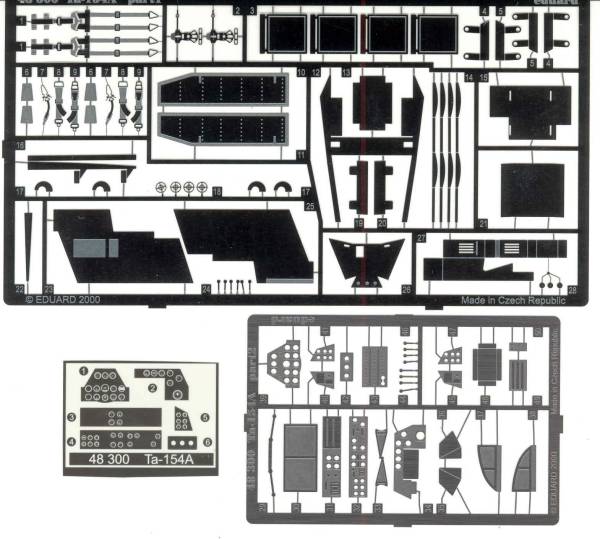
As is usually the case this set includes every thing but the kitchen sink and duplicates some of what was supplied in the above kit. Since it was intended to enhance parts that have been replaced they won't all be used. However it looks like to me that combining the two allows one to use what works best for them and there are a number of external parts in the Eduard that are not suppled in the CMK kit. One note the instruction sheet states that this is for the Hasegawa kit. I have never seen any reference to a 1/48 scale kit being released by Hasegawa but if it was it is most certainly the same Dragon kit. Hasegawa did do a 1/72 scale model. See below for a photo if the Eduard set parts.
The Eduard instruction sheet is standard for Eduard kits, a single A4 sized sheet printed front and back.
Cutting Edge VS 9 Propellers (CEC48168)
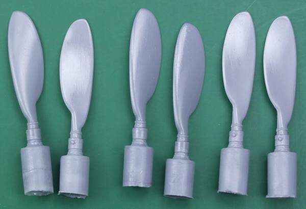
At least fourteen of the A-0 series aircraft and probably others were equipped with VS 9 propellers, these very wide chord props were most distinctive and I liked the look of power that they imply so I decided to go with the cutting edge set which are very nice. Molded in gray resin with no pin holes and only a minimum of flash. They are basically a drop in replacement for the kit parts. See below.
Terry Dean nose weights (which actually fit in the engine nacelles)
The Terry Dean weights are really slick. They are cast to fit in this case in the engine nacelles and provide enough weight to keep the nose firmly on the ground. You don't need to guess or mess around stuffing shot, wheel weights, fishing sinkers or nuts and bolts into nooks and crannies and hoping you have enough. Weights for other planes fit in noses or wheel wells and are made for aircraft in 1/72 and 1/48. If you haven't checked these out for yourself, give them a try.He doesn't have a website but you can see and read about them at this link over at Modeling Madness. See photo below for the set for this kit.
For those so inclined True Details makes a wheel set (48104) with smooth tread tires I found the kit wheels to be acceptable so didn't go with these.
Update Information
Within the past year or so Dragon decided to release this kit under its own brand name. the box heralds it as a 3 in 1 kit, basically meaning you can build three different versions, not three aircraft. With the parts supplied you can according to the box build the A-0 version, the V-1 version or the V-3 version. I did not bother to verify if everything you need for all three version are there, the primary differences are in the radar. The A-0 having the large "stag" antennas the V-1 have none and the V-3 having the smaller antennas from the earlier radar system. I bought the kit because it was heralded as a "new mold", note not new tool. Near as I have been able to determine the only thing new is a single small sprue that contains the antenna required for the V-3 version a different nose also for the V-3 version and a set of shrouds for the engine exhausts. All of the other sprues appear to be identical to the ProModeler release. It's difficult to tell if the issue with the wings is any better without actually assembling it but one can always hope. The kit also included a small fret of PR with alternative antenna. instrument panels and a couple other interior parts. The panels have the dials and pointers etched in, there is no film so I'm not sure its an improvement over the original. One also gets a new decal sheet with the makings for the additional aircraft. All in all I'm not impressed. Unless you are determined to build one of the "V" versions you are just as well off to buy the ProModeler kit as it can usually be found on ebay for less than the inflated price of the Dragon kit. Below are photos of the box and the new parts and decals.
Conclusions
In spite of its relatively lackluster career the Ta 154 certainly is a striking aircraft and the ProModeler kit seems to do it justice. Unfortunately the warped wing issue and other fit issues typical of Dragon designed kits detract some from the joy of building it. There certainly is a wealth of aftermarket goodies to dress it up and all in all it certainly won't be any tougher to build than many limited run kits. While I wouldn't recommend the kit to beginners anyone with a moderate amount of experience should not have that much trouble with it. I do recommend you read the reviews and builds in the links below to get a more complete picture of the fit issues with the kit.
Links to kit build or reviews
Reviews / builds can be found here, here, here and here.
References
"Monogram Close - Up 22 Moskito" by Jay P. Spenser
The Build
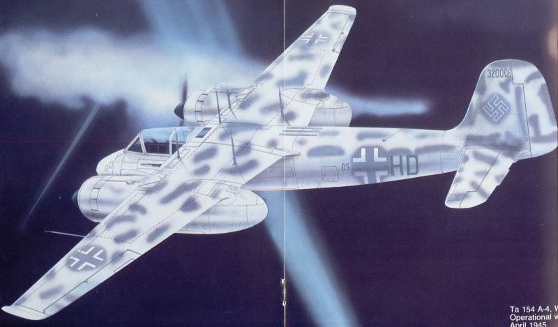
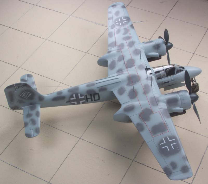
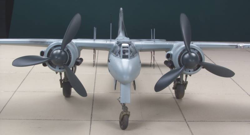
I decided I wanted to do something a little different on this kit and do a version not included as an option with either kit. I liked this artist impression of Wk # 320008 which depicts a late A-4 version which used FuG218 radar which used vertical mast antennas located above and below the wings and was fitted with upturned wing tips in an attempt to improve lateral stability caused by the total lack of dihedral of the wing.
The first step was to remove the molded in detail on the cockpit walls. It looks crude but it all gets covered.
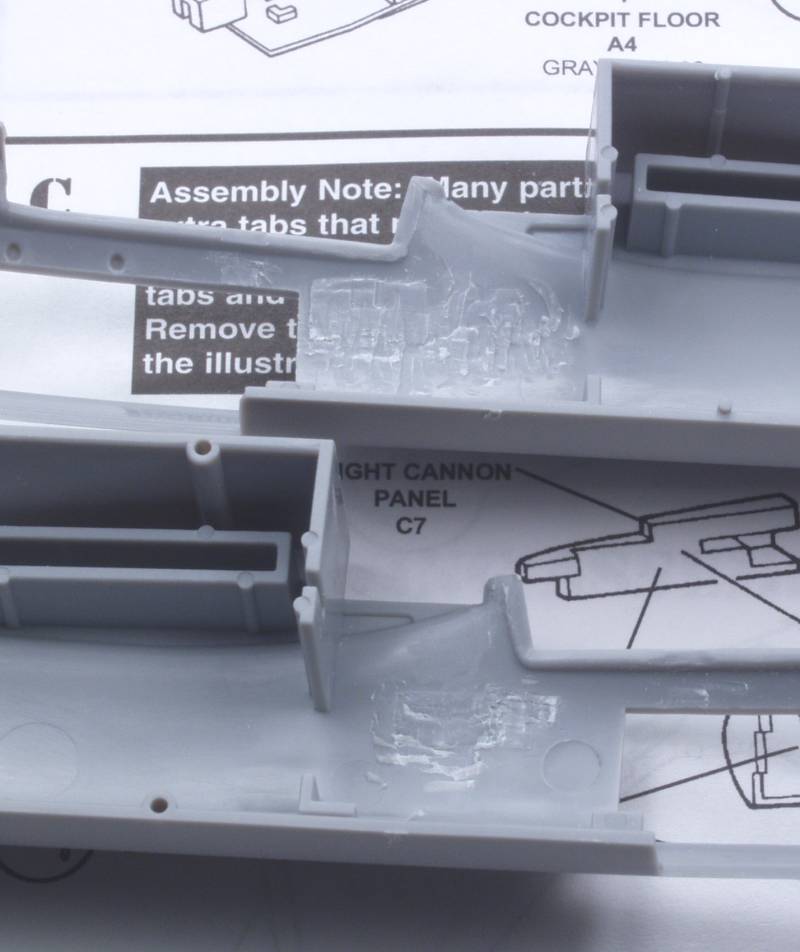
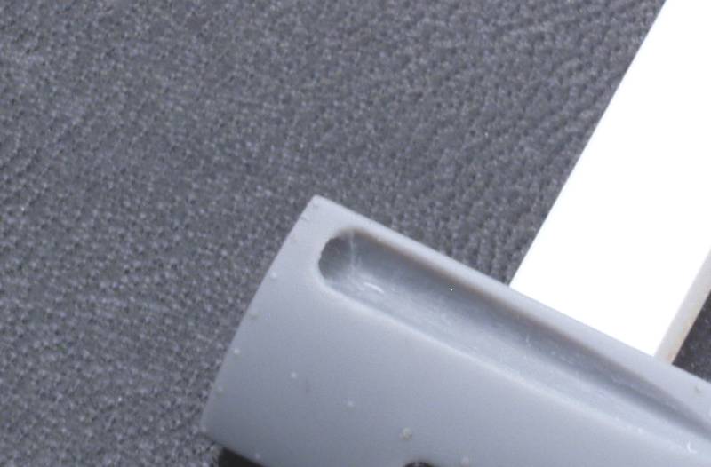
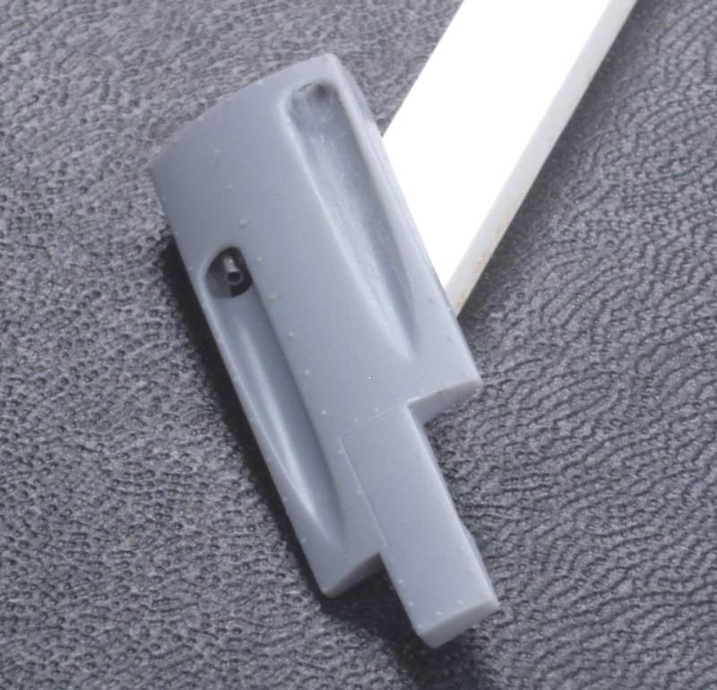
Before I installed the side panels I wanted to do something with the guns, I don't much like the molded on one and the opening needs a blast tube and the end of a gun barrel hiding in there.
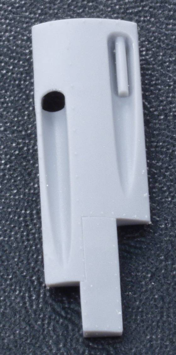
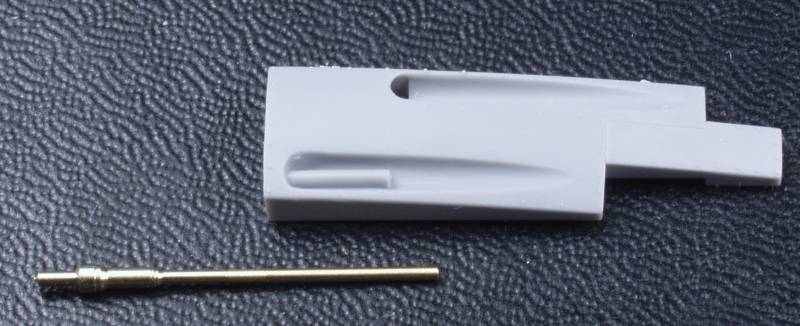
I wasn't sure how to go about removing the molded in gun barrel and retaining the radius behind the gun, I finally hit on the idea of using a piece of brass tubing the right diameter. I first sharpened the end of the tubing by using needle files to thin it down on the inside, then used it like a scraper to remove the gun down to the gun trough. While brass isn't all that hard, it's harder than the plastic and did the trick. I brushed some liquid cement over the area where the gun was to smooth it up. This will mostly be hidden by the new gun barrel.
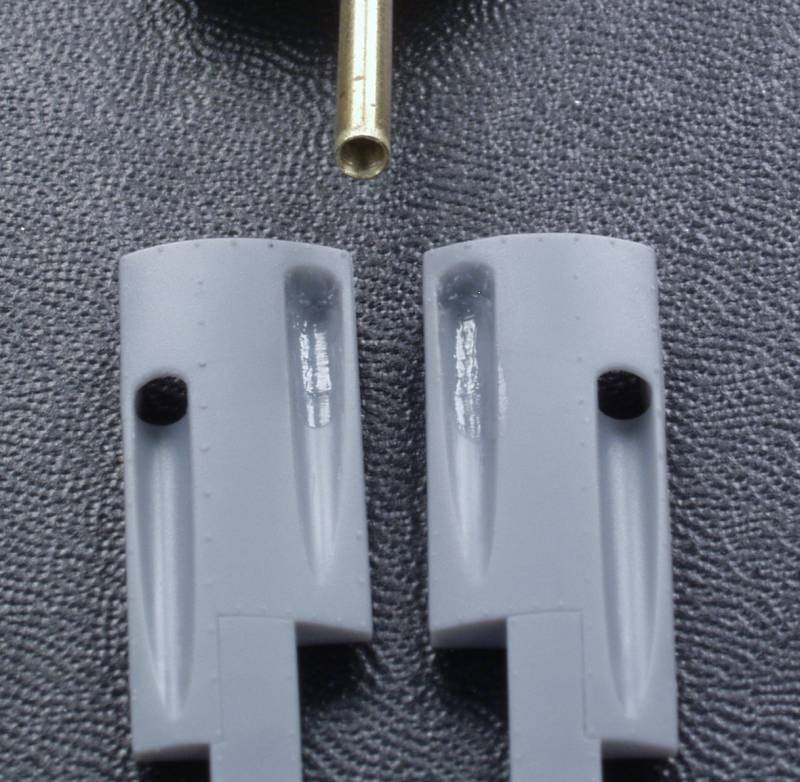
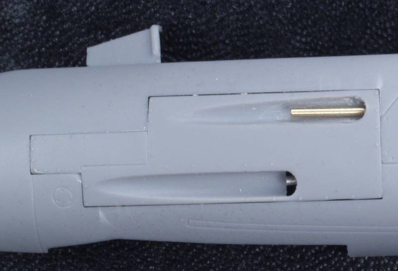
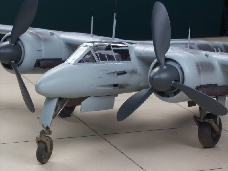
I decided to Master gun barrels to replace the removed 20mm guns. I had planned to just use hypo tubing but then AMS kicked in. While it doesn't show well, the Master barrels do have a slight taper to them and I always have an issue trying to get the end of hypo tubing to look right, the master barrels have a nice radius and bore on the end that looks like a gun barrel and not like a piece of cut off hypo tubing. In any event I think it looks better than it was represented on the kit part. Now I just need to bore out a blast tube for it.
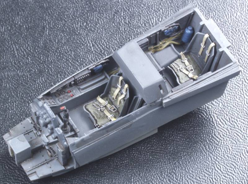
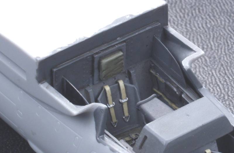
Cockpit completed as far as I could without inserting in the fuselage.
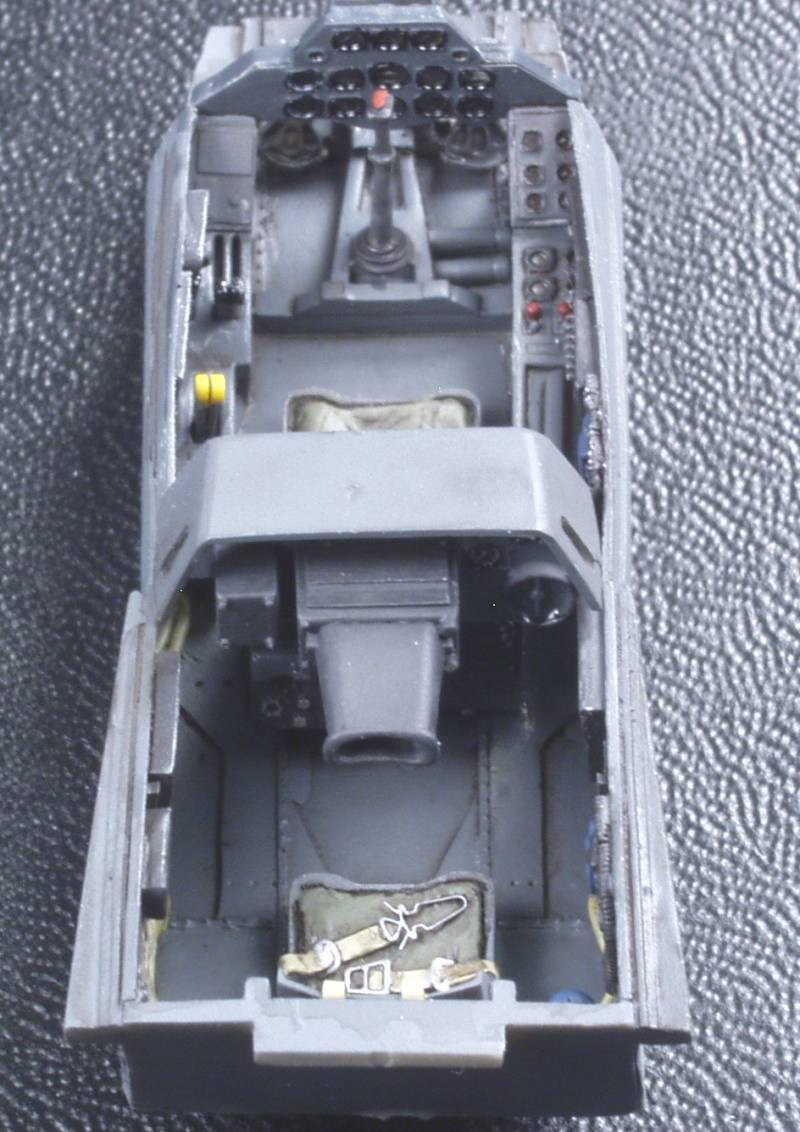
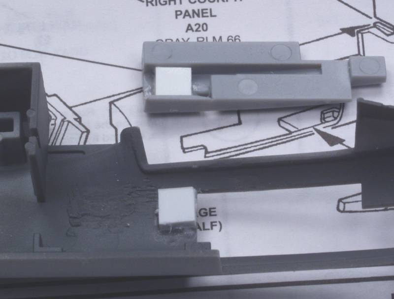
Very difficult to tell what is visible in the 30mm trough but the gun barrel doesn't look to protrude very far if at all so all I want there is the end of a gun barrel. The 20 mm appears to be coming out of a blast tube and the way the panel is molded it doesn't look that way and just drilling a hole to plug the barrel in didn't look right to me. I drilled a hole for the 20mm with the panel in place on the fuselage to see where it came out, then blocks of styrene were glued on the fuselage were the gun would penetrate and also on the gun panel behind the opening for the 30mm. It probably would have looked better to fill the hole and re drill it due to the odd shape there but I think once the internal area is painted flat black it won't matter.
I then made a 30mm barrel from a correct ID piece of hypodermic tubing, drilled a hole in the block I had glued inside and pushed it in place.
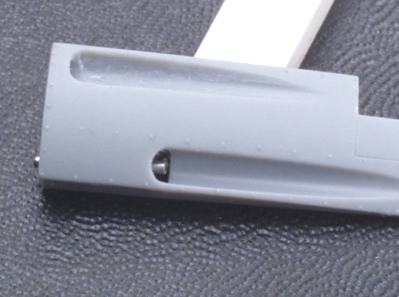
I may leave it out a bit farther, it's just test fitted for now, I'll leave it out till after painting. Here is how it will look with the 20mm in place.
The panels and pit were installed and fuselage glued up. The last couple of fuselage bits were then installed, the rear bulkhead with the radar operators head rest which does a nice job of hiding most of the fuselage seam and a couple of pieces of PE that add some structural detail and hide part of the wing root. Not sure how visible these will be, I guess I will find out when the canopy goes on.
As mentioned in the review the kit has an issue with the wings. If you just glue them together right out of the box they sag, a negative dihedral where there is supposed to be none. It has been speculated that this was caused by popping the parts out of the mold too soon however I'm not so inclined to go along with that as the much later release by Dragon exhibits the same problem. My theory is that it has to do with stresses in the part due to the wings being rather thin outboard of the nacelle area which is much thicker. Anyway here is what you get out of the box.
A rather poor photo but you get the idea. Before doing anything else I tried the hot water treatment and careful bending. This helped some but did not solve the issue and it left some stress marks in the thick area around the nacelle, fortunately on the inside.
I decided to use the method Tom Cleaver did using a coat hanger as a stiffener. I first determined how far out in the wing it would go without interfering with the wing halves. I then cut a length of coat hanger they required length to extend from one wing to the other making certain it was straight. Once I determined where it would lay I drilled a hole through the wing roots and fuselage. I test fitted everything before the next step to make certain there were no fit issues. I next glued the coat hanger to one wing using 5 minute epoxy and clamped it to a flat surface until it cured.
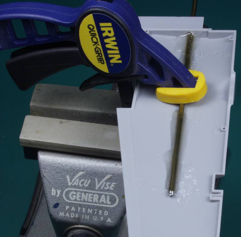
Once it cured the next step was to slide the coat hanger through the fuselage and glue the wing root and the lower wing root to the fuselage making certain every thing fit properly. while this was still soft the other upper wing half was slid onto the coat hanger and its wing root glued to the fuselage along with the lower wing root. Another batch of epoxy was mixed and the coat hanger glued to the inside of the other wing and the whole assembly was clamped in place to a brass bar to keep the upper surface of the wing flat until it cured over night.
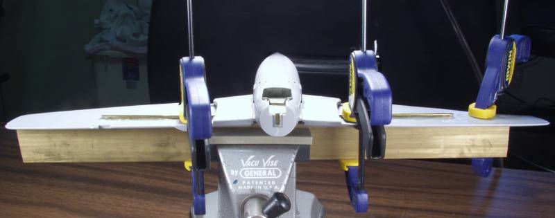
Once everything was set up the rest of the lower wing parts were installed as well as most of the rest of the airframe parts.
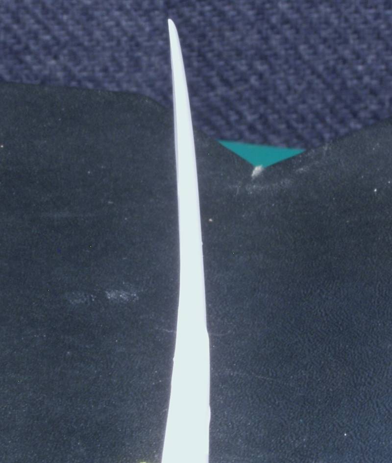
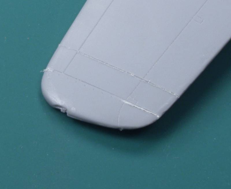
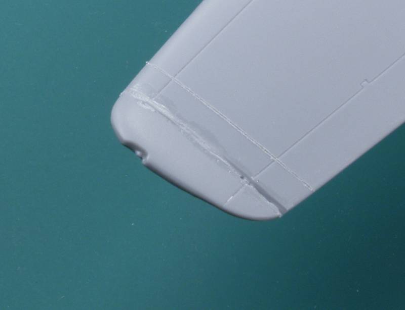
I spite of the optical effect the wing is straight! Note that the dymo tape on the wings is the prelude for the next step. Now that the wings are straight, I'm going to bend them but only the tips this time. The bird I'm modeling was one of several fitted with up turned wing tips in an effort to improve directional stability. Wings with no dihedral almost always lead to directional instability but I assume in this case it was done for strength and easy of manufacture. The tape was use to scribe a new panel line where the new tips attached. The original wings had the ailerons going all the way to the tip but now they need to end before that. The new line was marked and scribed using measurements from a scaled up drawing.
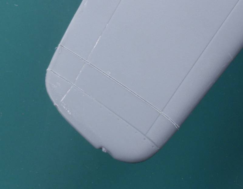
Once that was done a saw cut was made on the top using the existing panel line.
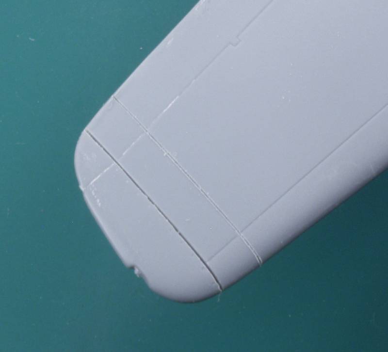
This was cut all the way through the top wing and into the leading and trailing edge on the bottom wing. I just wanted to leave the center of the bottom wing to act as a hinge.
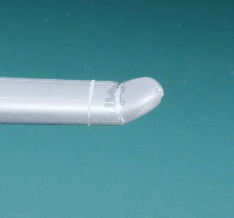
Next the dymo tape came back out to mark another location topside. This was first scribed then a saw cut started.
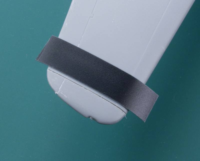
Once started I tilted the saw at 45 degrees and cut towards the first cut until I had removed a wedge on material.
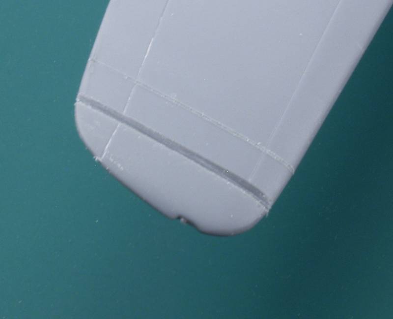
then scribed the lower panel line to make it deeper and
the part thinner then applied several coats of Tenax to soften it up. I
then saturated the upper portion and using brute force, bent the wing
tip up and held it in place until it hardened up. The process was
repeated on the other wing.
While it looks ugly at this point once it's all filled and sanded all
should be good.
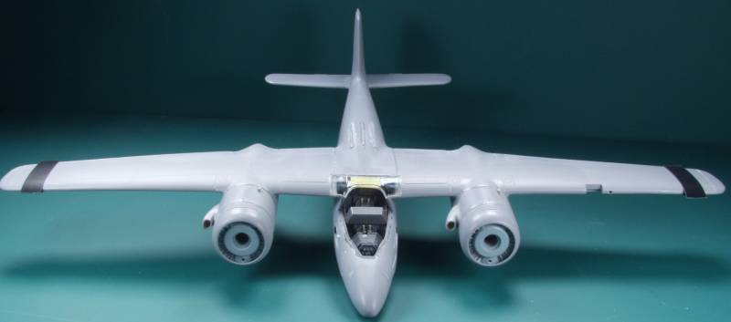
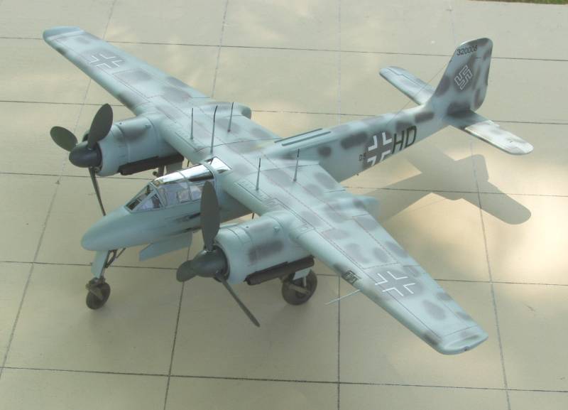
From here it was on to the body and paint shop, I didn't take a lot of photos here. Not much to see watching paint dry. I spent a lot of time cutting out a mask for the mottles on the upper surface but in the end decided to go with free hand and I'm glad I did as I was quite happy with the end results.
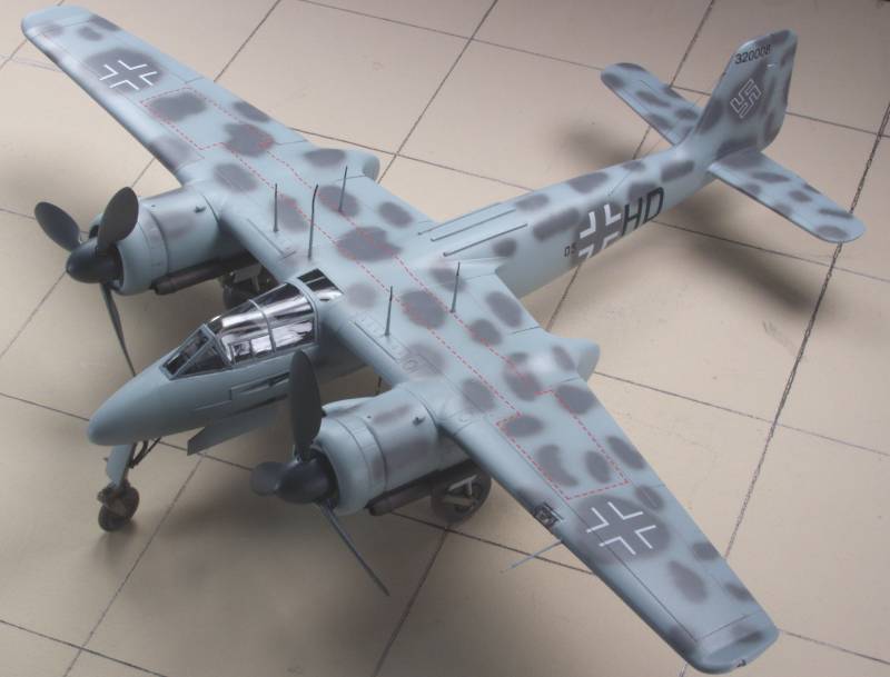
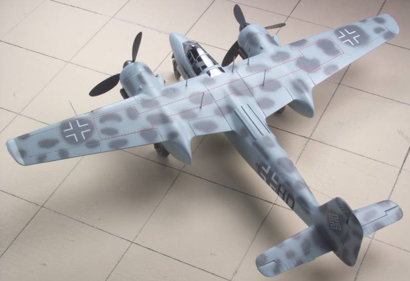
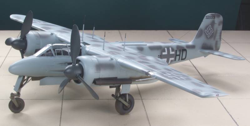
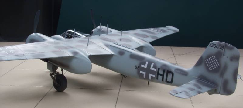
And a few shots in natural light.
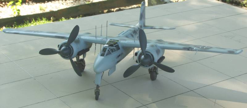
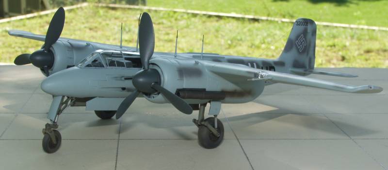
Except for the wing issue the kit actually goes together quite well. I did modify the stance by shortening the mounting block on the main gear by .062" and added a .062 spacer to the bottom of the nose gear. The vertical antenna turned out to be a PITA but I like the look better than the traditional stag horn antennas. The Terry Dean weights along with the resin pit and props provided more than enough weight to keep it on its nose and it will even return there if you push the tail to ground and let it go. All in all it was a fun experience and I'm happy with the end result.
Back to the Night Fighter page
Updated 9/25/12