
Bf 109E-4
As
one of the most well known aircraft of WWII, I'm not going to go into
history here. There is plenty of material available on it on the web
and else where. The E-4 version was one the most numerous versions that
was used during the Battle of Britain and that along with being one of the newer "state of the art" kits were my main reasons
for wanting to build this kit.
The Kit
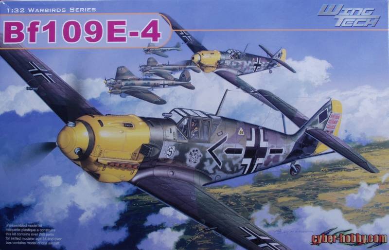
The Cyber-Hobby Bf 109E-4 comes in a large top open tray style box with attractive artwork on the front. Cyber-Hobby for those who don't know is a division of Dragon Models. Upon opening the box one finds a cardboard insert to which is attached four clear bags, two which have zip lock tops and contain, photo etch frets, one sealed bag has the two flexible plastic gear well liners and the last sealed bag has the decal sheets, one large with the main markings and a smaller sheet with unit markings, stencils and kill markings. I like this method of packing as it keeps these parts from being damaged in shipping. Under that there are three large cello bags with two sprues each in gray, one small cello bag with two sprues in gray and two small bags with clear parts in them. This kit is a very recent issue and uses all the latest molding technology to render fine details such as slide molding to provide hollow ends on exhaust stacks and guns.
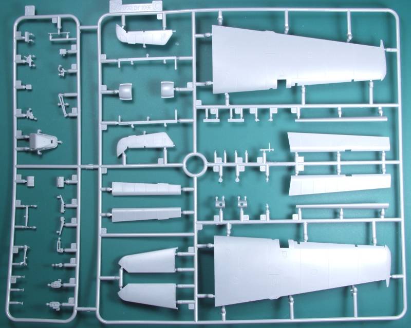
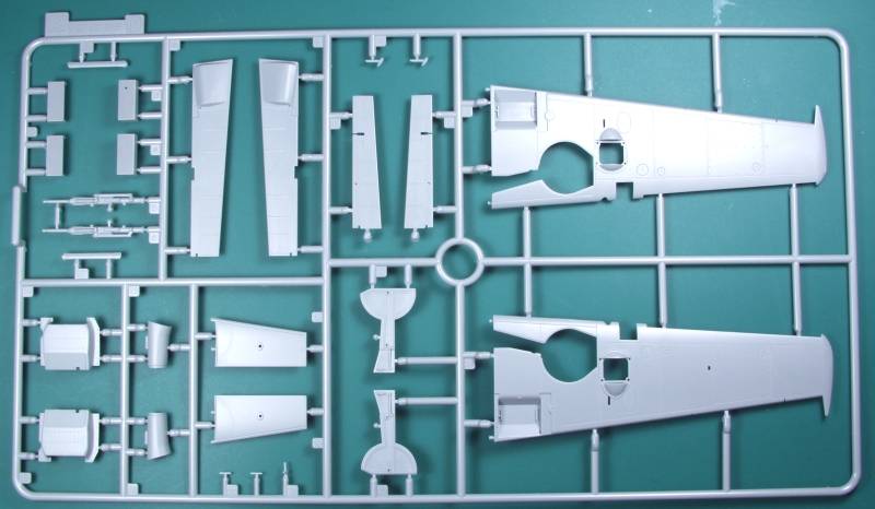
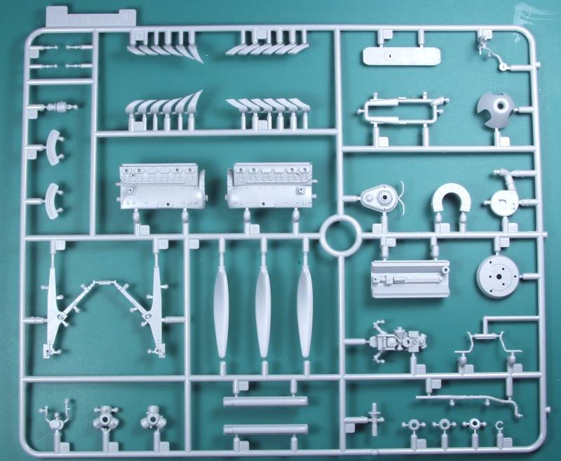
Looking over the parts they are virtually flash free and feature very fine detail. Panel lines are recessed, fine and discrete, flush rivets are represented with recessed holes and these to are very nicely done. There are also raised rivets where appropriate such as on the inside of the landing gear doors and on the under wing radiator covers. Ailerons, flaps, elevators, leading edge slats and rudder are all separate so the can be positioned as desired and the fabric portions are very subtle. With the exception of the slats the movable surfaces use PE and plastic parts that can be a real test of patience to assemble. There is no mention of displaying the flaps open in the instructions and there are ejector pin marks on the inside of the flaps should you want to do so. With a little modification and some careful gluing the slats can be made movable and the advantage there is that they can be closed during painting then posed in the open position when the painting is completed as they would normally be when the aircraft is on the ground. The plastic has a satin finish to it that feels smooth to the touch. While the sprue gates on parts such as the wings and fuselage are situated on the glue surfaces where they will be hidden once assembled, on many of the small parts the sprue gates are rather heavy and some care will be required when removing them. Other than inside the flaps most other visible surfaces are free of them. There are a number of optional parts supplied as well as parts aimed at other versions not included in this kit. The engine is a complete kit in itself should you decide to display the aircraft with the cowling off. There is an error on the elevators on sprue C, the trim tabs need to be located one rib in further. Fixing this is a simple matter of trimming off the tabs and replacing them in the correct position with some thin styrene. Another known error is that the rudder hinge locations don't match up with the hinge locating holes in the fuselage. again this is a relatively easy fix if you know about it in advance.
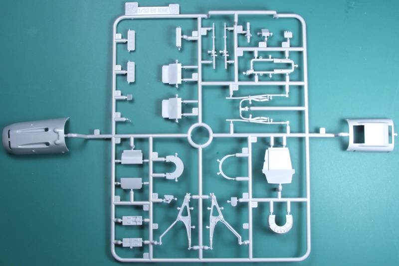
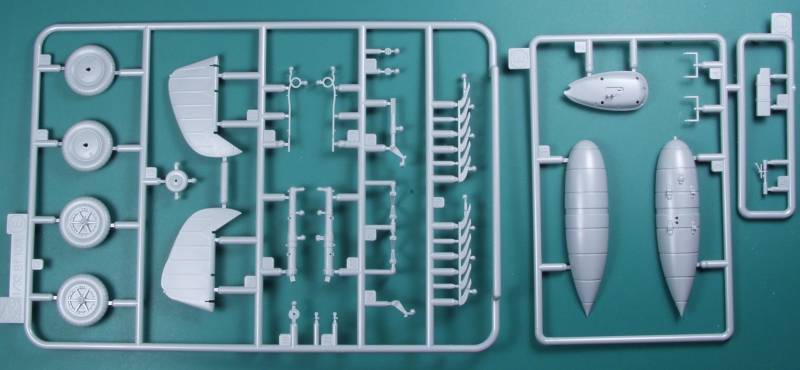
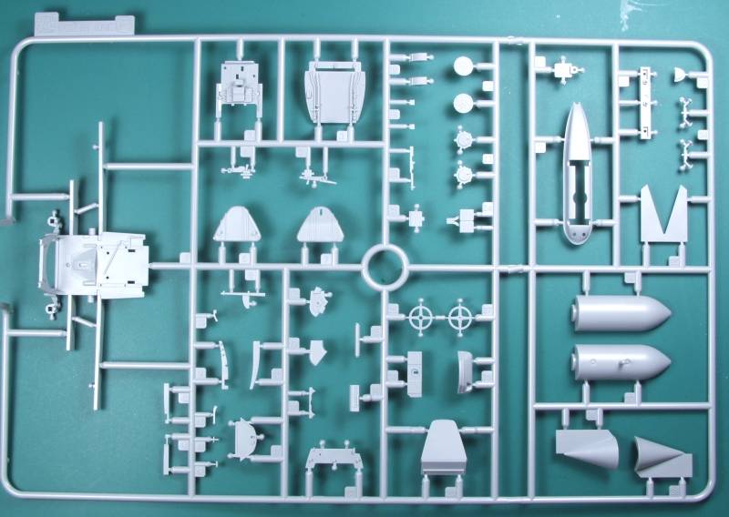
Shown below are the sprues in order starting with A
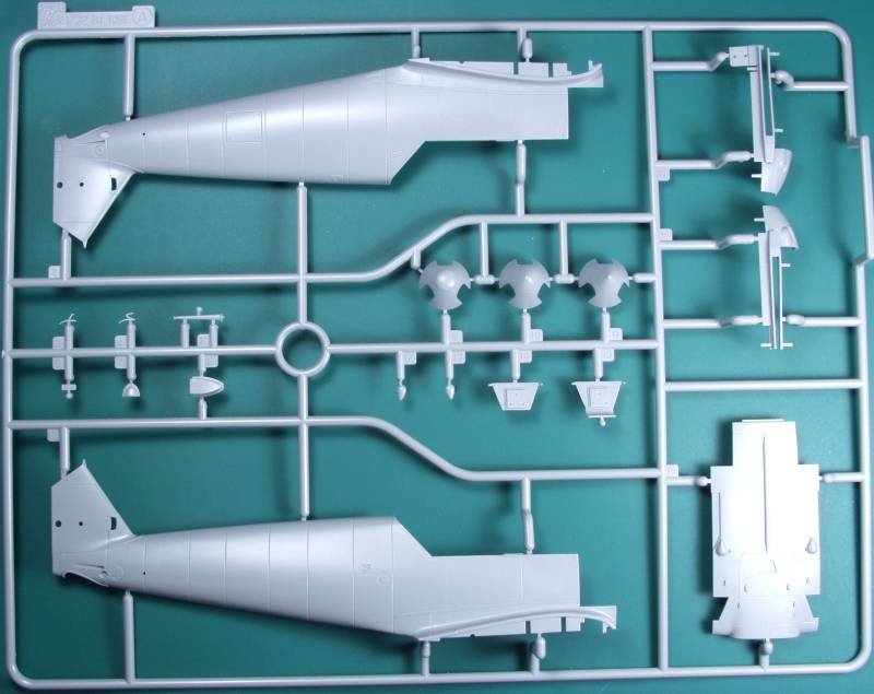
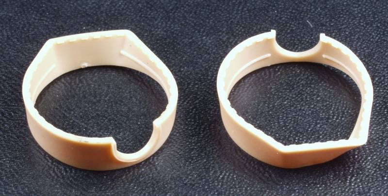
Two parts are molded from a proprietary vinyl material, these are the canvas boots that normally line the landing gear wells. The advantage in doing it this way rather than using styrene was the ability to make it in one piece, eliminating the difficult to hide seam you would get with two styrene parts and yet be able to mold detail all the way around the inside. also being some what flexible make fitting easier.
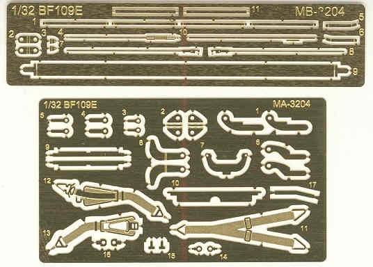
The photo etch parts are on two frets, the first one shown has parts that are used on the external drop tank and bomb and the safety line that restrains the canopy in the open position as well as a couple other cockpit parts, the second fret has the harness and belts and hinges for the movable control surfaces. See below.
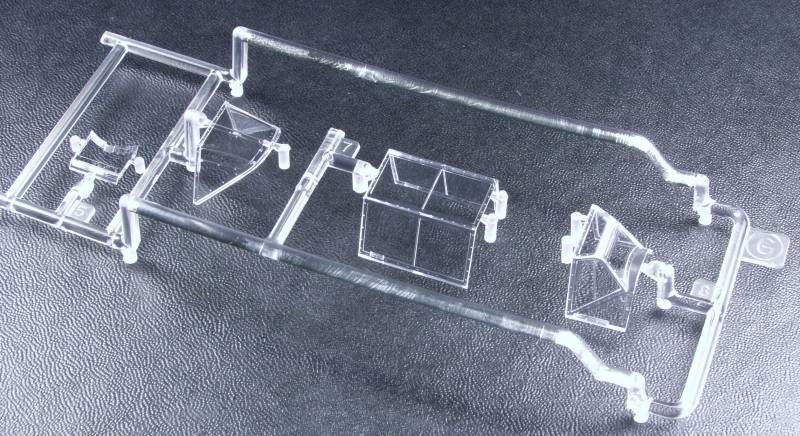
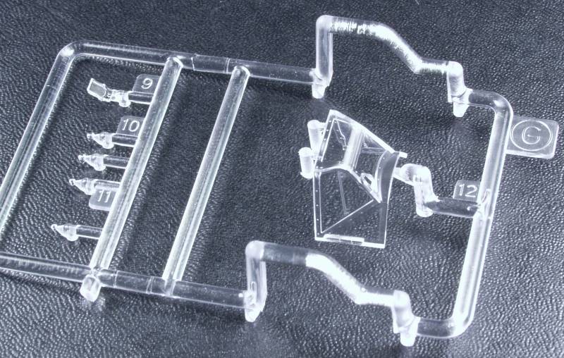
The clear parts are thin and reasonably clear with only minimal distortion. an extra front windscreen is included if you decide to built the Galland version which used a telescope to aid in identifying other aircraft from a distance as well as the normal reflector type gun site. Note the telescope was not a gun site. Also included on the clear parts sprue is the armored glass for behind the windscreen and lenses for the marker lights. See below.
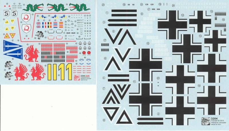
The decals are thin, matte in register and lacking swastikas. A fair amount of stenciling is also provided. They are printed by Cartograf who has a good reputation for producing nicely behaving and well printed decals. Five options are provided, Oberst Aldolf Galland, JG 26,Hauptmann Rolf Pingel, 1./JG 26, Hauptmann Gunther Lutzow, 1./JG 3, Oberleutnant Gerhard Schopfel, 9./JG 26 and Major Helmut Wick, JG 2. See below.
The instructions, printed on a large folded sheet divided into ten panels with most panels having more than one step on them. The instructions have the now common place parts maps with parts not intended for this kit marked out in color. Also included is a color chart calling out Grunze colors and the usual icon map and safety warnings. The assembly instructions appear clear enough but are a major let down. Color call outs are few and far between so have your references at hand. In some areas detail as to the fit of some parts is ambiguous. There are two parts that are intended to fill the gaps between the cockpit floor and the fuselage that I have read are shown reversed. I could not get them to fit no matter how I placed them and eventually tossed them. Some of the part locater pins fit loose enough that care and fitting are required to make certain they will not interfere with later assembly. Parts A12 and A13 are shown attached to the bottom portion of the fuselage when they actually go on the wing fillet. Also the order of assembly can cause you issues further along and I would definitely not attach the lower fuselage section A19 to the cockpit sub assembly as called out or you'll likely have fit issues with the wings at the root. Leave this part off till after you attach the wings to the fuselage, then make adjustments to the part to make it fit. I found in my case the front part was a bit too wide and needed to filed down a bit. I would advise trial fitting some of these parts before blindly following the instructions. Overall the instructions were one of the let downs of the kit for me.
After Market Goodies
Eduard, as usual, has produced photo etch sets for this kit. I did decide to use the Zoom set, primarily for the instrument panel and the painted seat belts and harness as the kit parts need to be painted. If you prefer to anneal your PE belts to make them more flexible then by all means use the kit parts.
Conclusions
For the most part I was disappointed in the kit on the whole. I bought it assuming as a state of the art kit it would have not only a high level of detail but sterling fit as well. Such was not the case as you'll read in my assembly log following this review. The parts themselves are all very nicely molded with minimal flash, I found that the parting line flash on some of the parts was so fine I didn't see it until after I painted the parts. Most everything from the cockpit back fit like a jewel. If you are planning to build this kit with the cowlings all off to display the lovely engine and piping detail, I believe you'll be quite happy with the kit as that area is very complete and would require only the addition of some wiring and some of the minor plumbing to be a real museum quality kit. However, if you wish to build the kit all buttoned up, as I did, you are likely to be less than satisfied. Not only will the assembly order make your life miserable but the fit of the cowling parts is just poor. Especially the main upper cowl which is nearly 1/16" too short. Personally I find this to just be unacceptable for a new state of the art kit and one that is not necessarily inexpensive at that. There is more on the fit issues in the assembly log following this review. You have been warned.
Links to kit build or reviews
An additional in box review can be found here.
References
Tons of references out there but one I found that was most helpful was Squadron / Signal Publications Walk Around Number 34 Messerschmitt Bf 109 E
Back to the 1/32 Scale German Aircraft Page
The Build
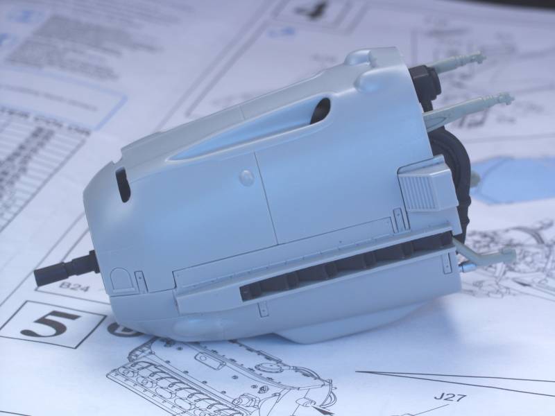
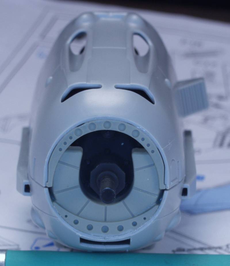
It was my intension from the outset to build this kit all closed up in spite of all the nice internal detailing. The engine and pieces parts were painted basic colors and the cowling parts installed. As can be seen in the next three photos everything fit rather tidily.
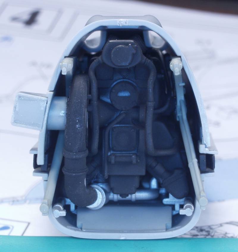
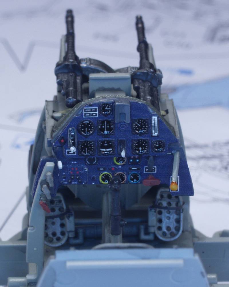
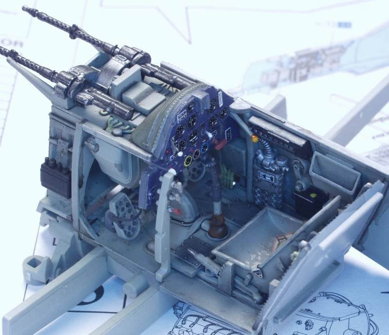
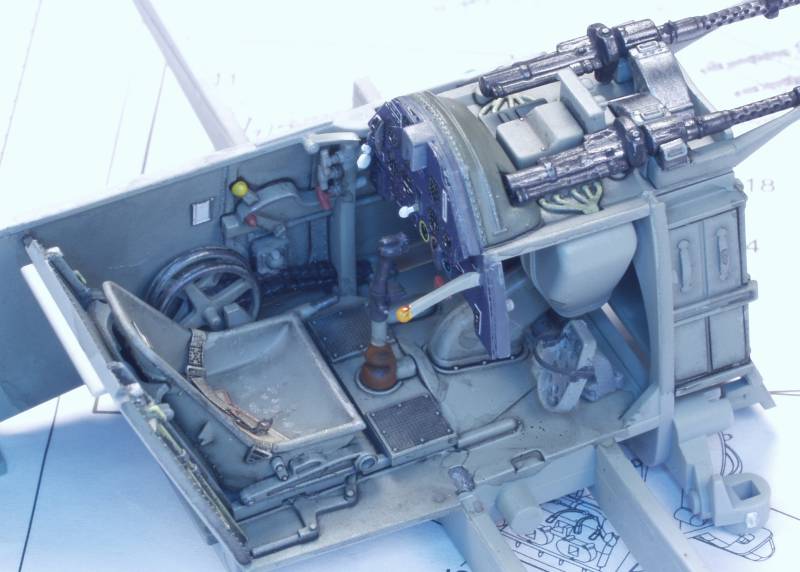
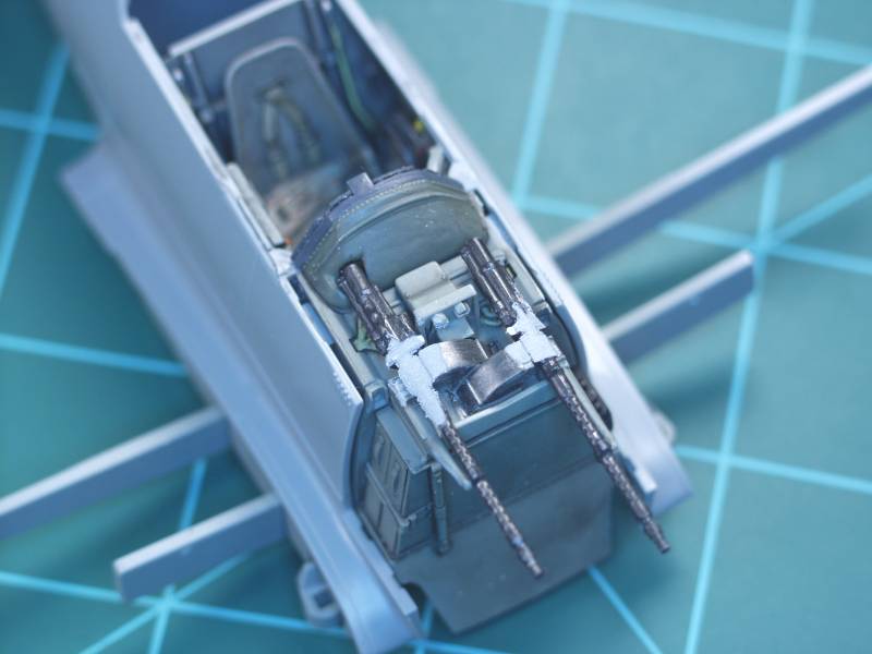
Next up was the cockpit and gun bay. Again the detail is quite nice but some of the part placements were a bit fiddly and care had to be taken as some of the parts fit their alignment pins rather sloppily and could cause issues later on if some test fitting is not done. The Eduard instrument panel makes into a lovely piece. The level of detail can be seen in the next seven photos.
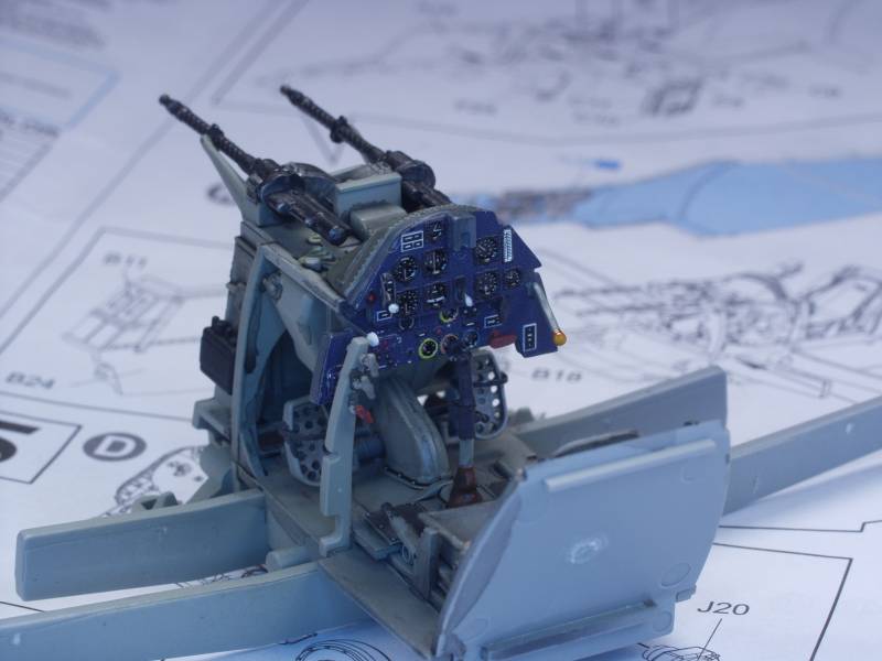
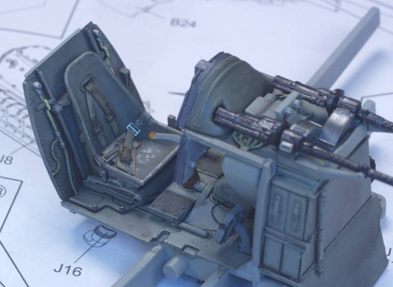
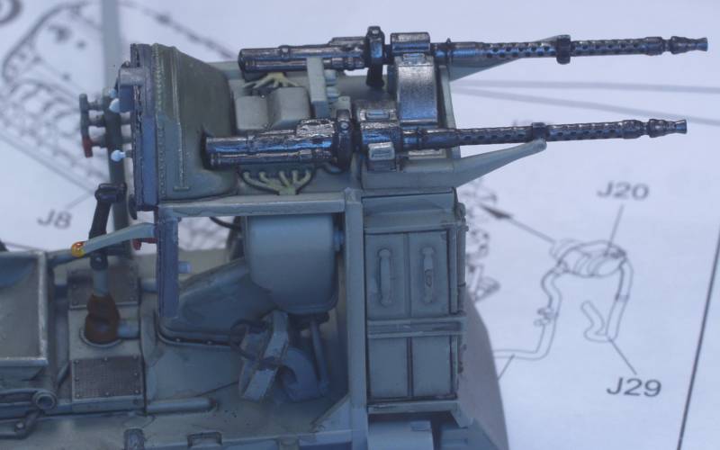

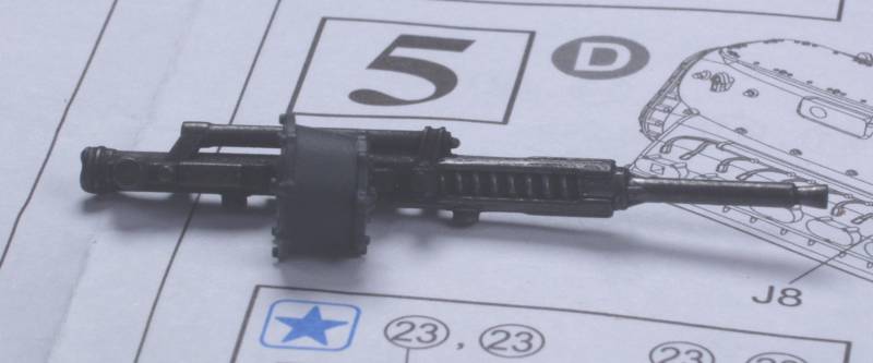
Even the wing guns are nicely done although all you will see is the barrel.
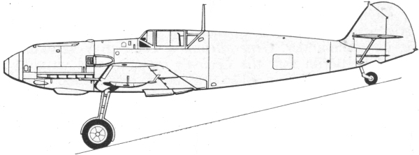
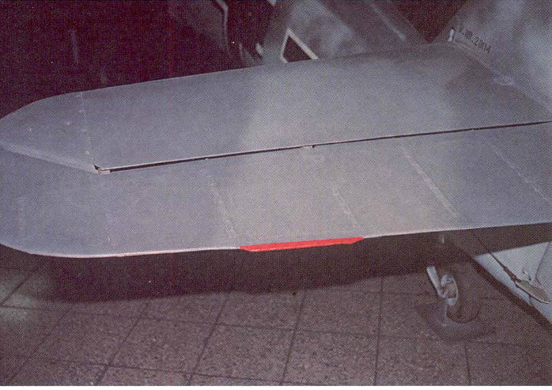
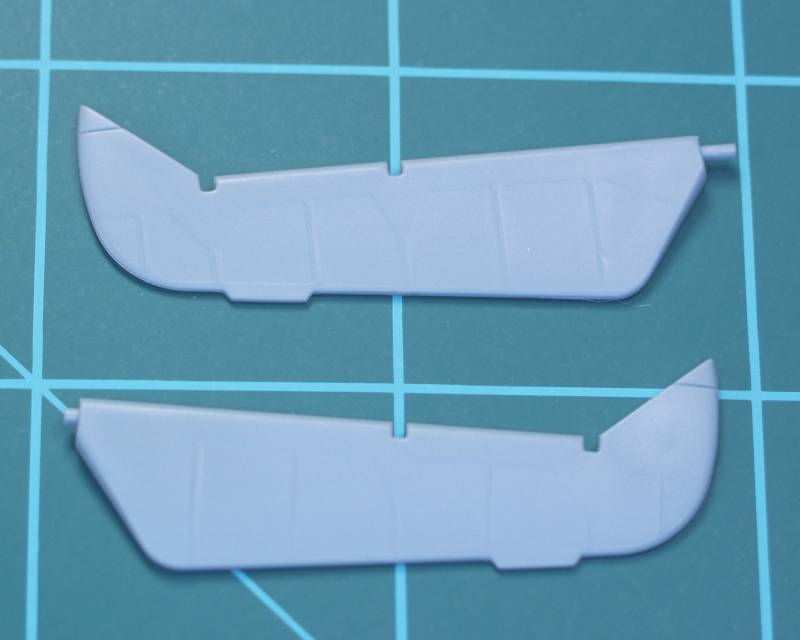
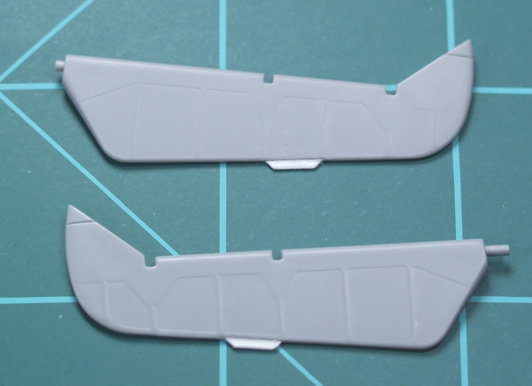
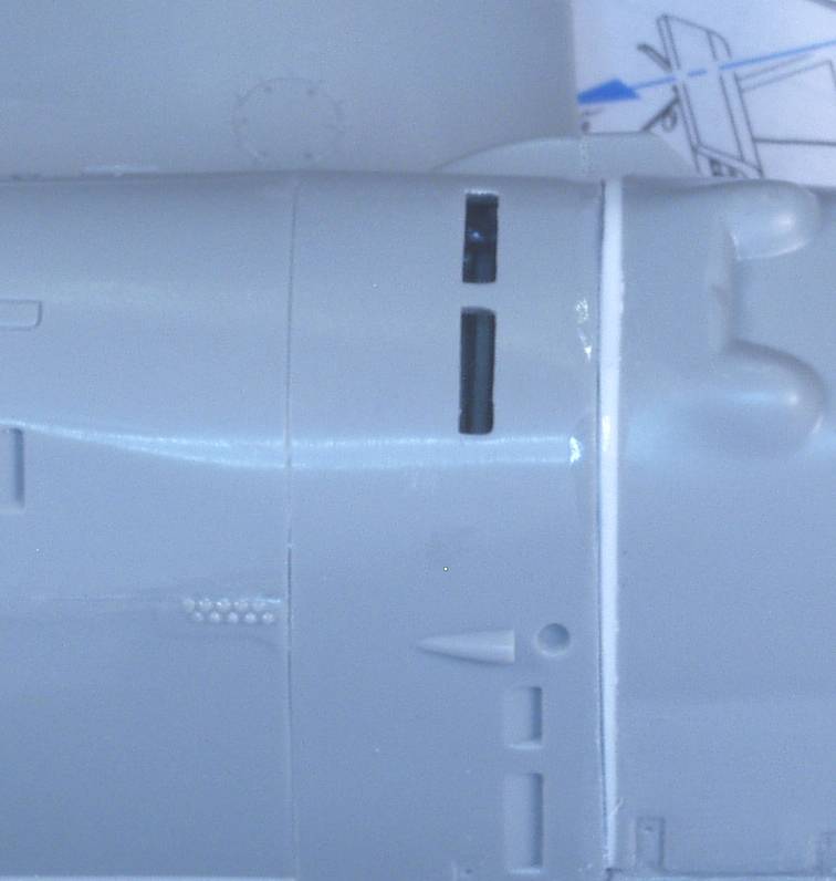
One
of the kit's issues is the placement on the elevator trim tabs which
were incorrectly located. This was an easy enough fix, just a matter of
trimming them off and replacing them with some bits of styrene sheet in
the correct locations. The next three photos show the correct location
on the prototype and the kit pieces before and after.
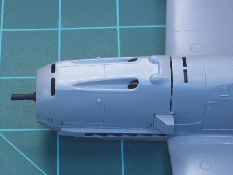
Assembly problems started when test fitting the cowl over the gun bay. It just didn't fit. Interference with the guns turned out to be the problem and solving it required filing away some of the lovely gun detail
While the instructions would have you glue the gun bay cover in place prior to installing the engine assembly I would recommend against it as it makes it nearly impossible to see whether or not the engine bearers are properly seated into their mounting sockets and as you will see this is very important. Even with them properly seated you are still likely to end up with a large gap between the engine cowl and the gun bay cover as shown in the next photo. One possible fix would be to shorten the engine bearers.
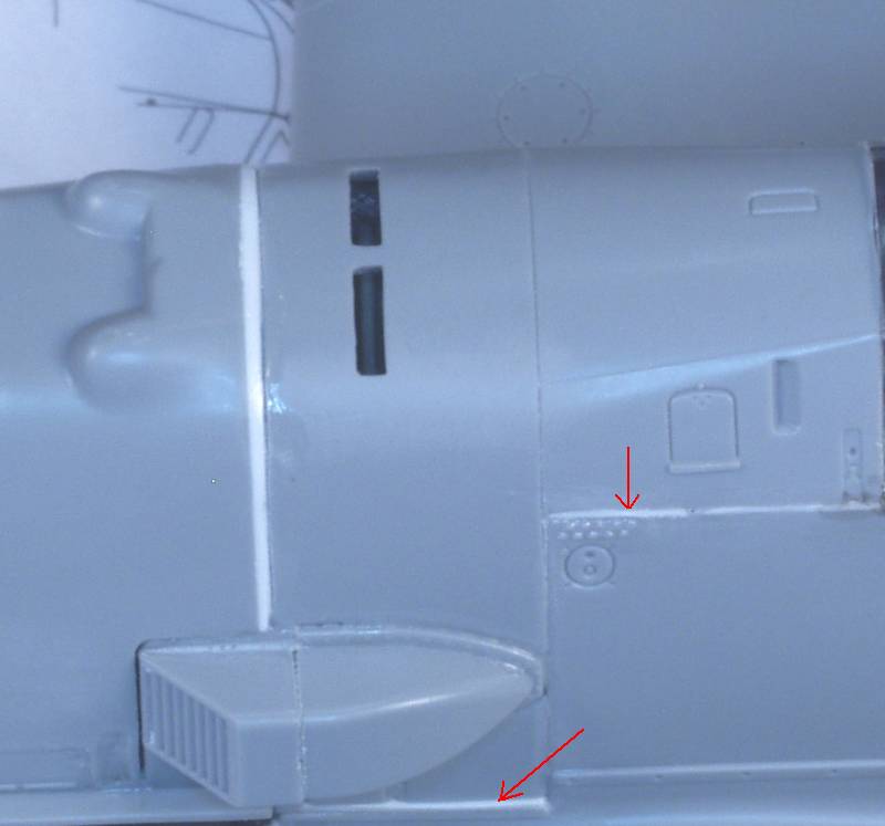
In
my case I just filled the gap by first gluing a sheet of styrene the
necessary thickness to the back of the engine cowl, when this was
thoroughly set up I carved away the inside area to match the cowl then
sanded it so that it filled the slightly tapered gap between the engine
cowl and gun bay cover. I also need to fill a couple minor gaps on the
gun bay cover with styrene shims. All of this is illustrated in the
next several photos.
Once I was happy with all the gap filling a coat of Mr. Surfacer 1000 was applied as a primer.
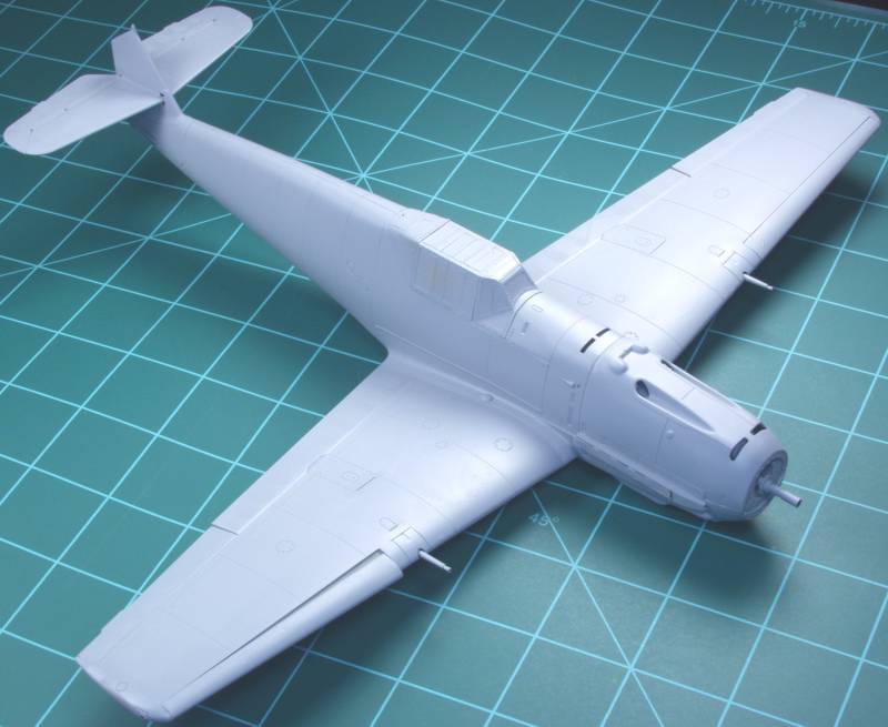
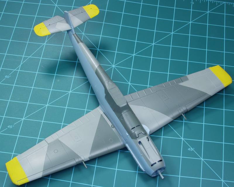
Next the yellow trim was painted on.
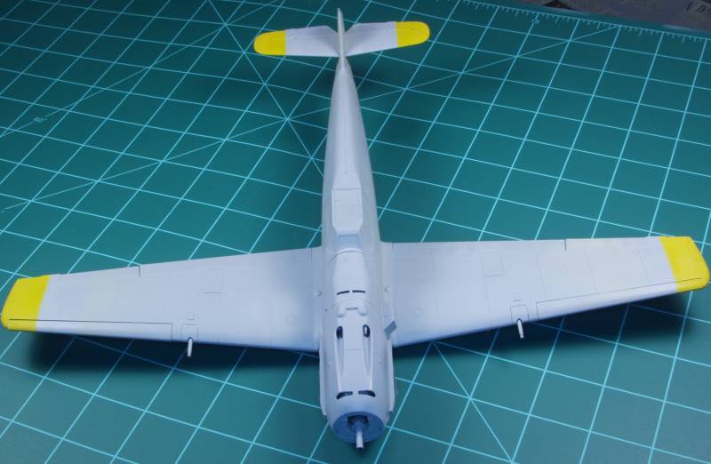
Then masked off and the RLM 65 applied.
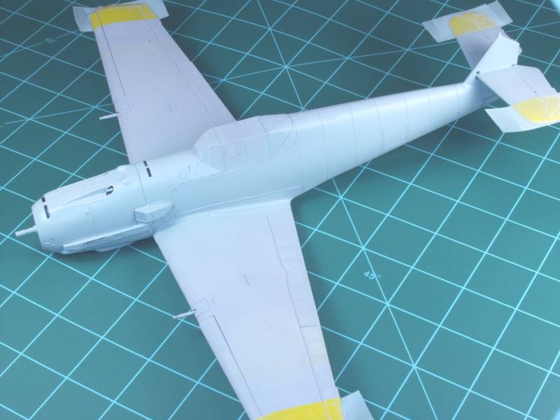
Followed by RLM 02 and RLM 71.
Then on to the decals. The kit decals were printed by Cartograph and were most excellent going on ans settling down with only a little Microset being used during application.
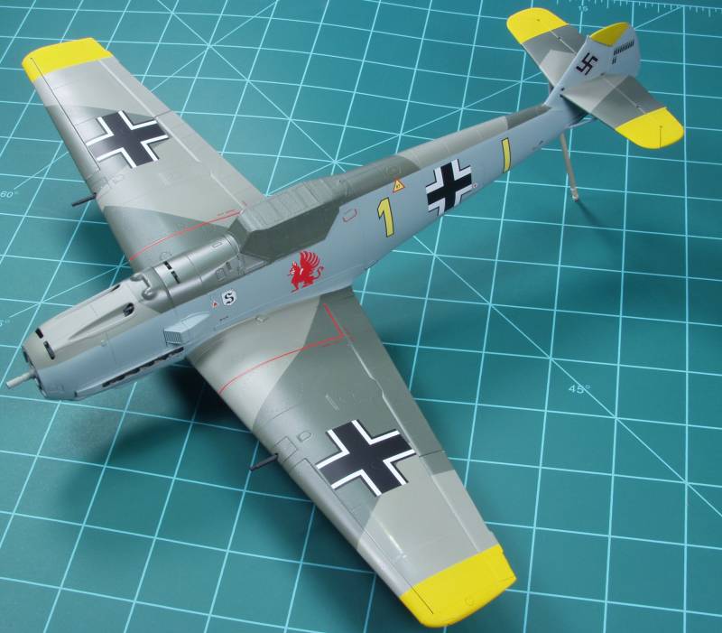
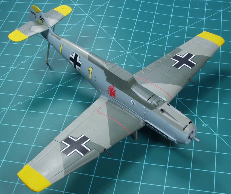
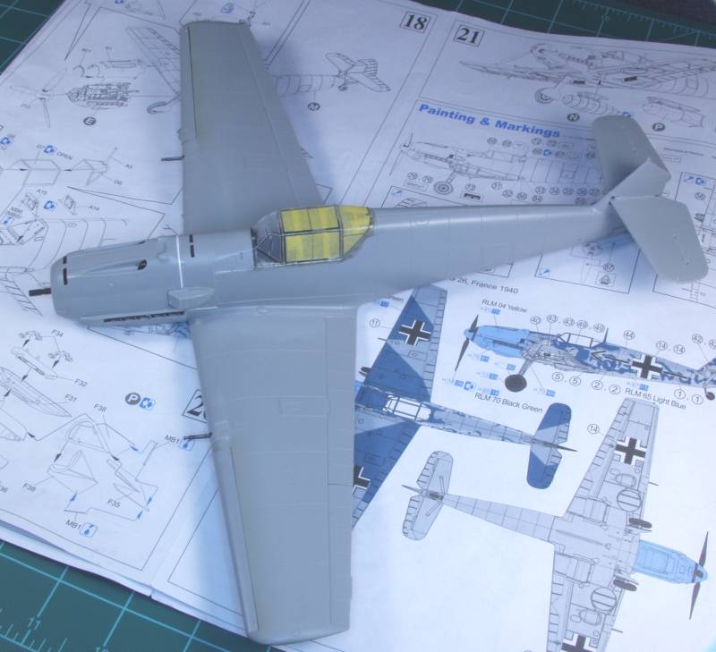
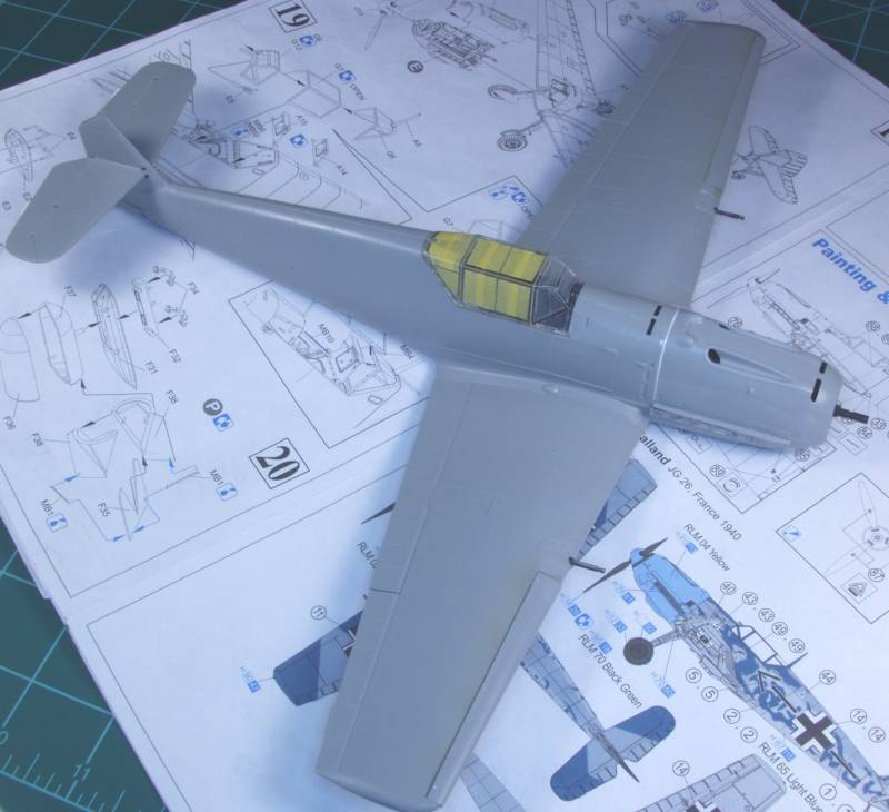
The next several photos show the model complete with the exception of the antenna. I found some issues with fogging on the inside of the canopy when I unmasked it and decided to strip, remask and repaint it before installing the antenna.
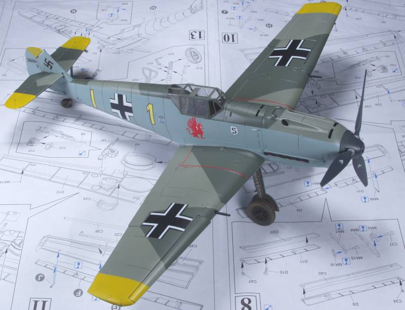
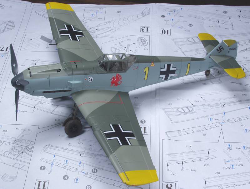
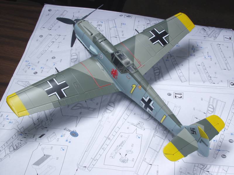
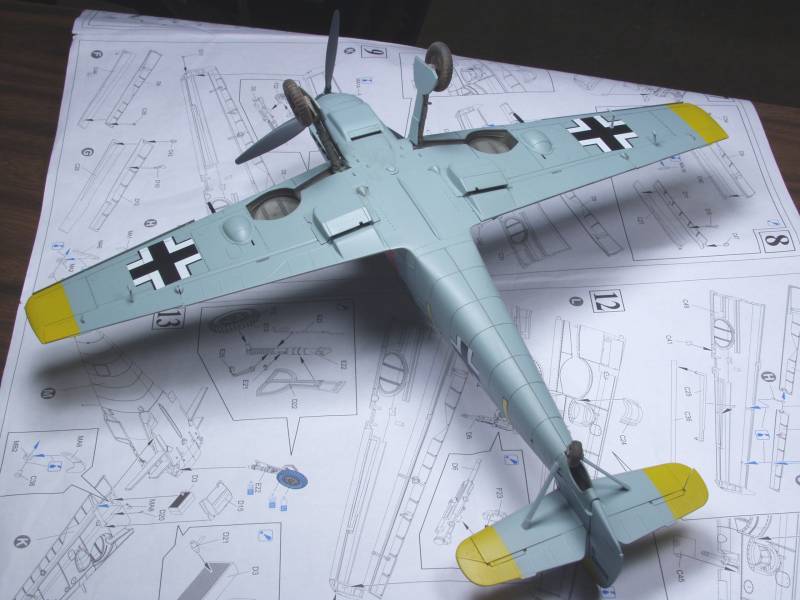
The last two photos show it complete. I did not due a lot of weathering as I felt at this stage of the war things were probably keep up pretty well. That's my story and I'm sticking with it.
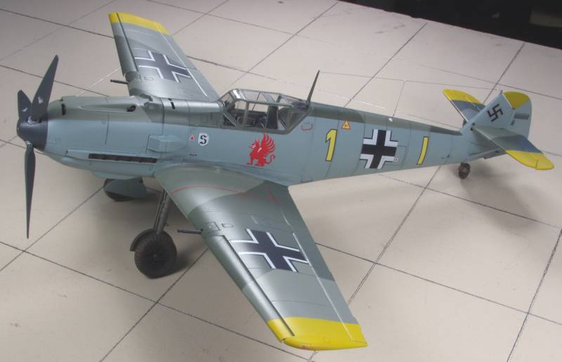
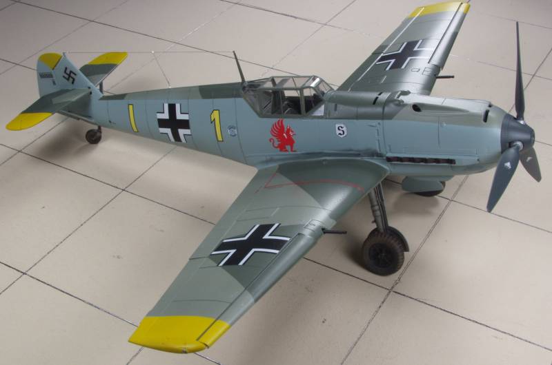
The kit does produce a lovely model but it was difficult in places I felt it shouldn't have been and as I mentioned in the conclusions at the end of the review it would be a great model to build if you want every thing opened up as it would bypass the issue you run into building all closed up.
Back to the 1/32 German Aircraft Page