TBM-3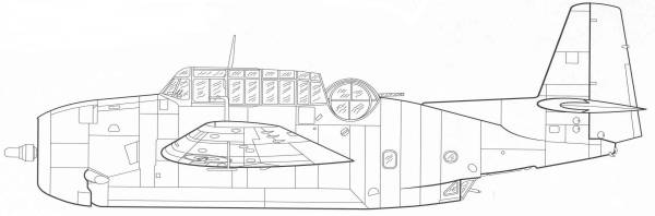
The Douglas' TBD Devastator, the U.S. Navy's main torpedo bomber introduced in 1935, was obsolete by 1939. Bids were accepted from several companies, but Grumman's TBF design was selected as the replacement for the TBD and in April 1940 two prototypes were ordered by the Navy. Designed by Leroy Grumman, the first prototype was called the XTBF-1. It was first flown on 7 August 1941. Although one of the first two prototypes crashed near Brentwood, New York, rapid production continued. Grumman's first torpedo bomber was the heaviest single-engined aircraft of World War II, and only the USAAF's P-47 Thunderbolt came close to equaling it in maximum loaded weight among all single-engined fighters, being only some 400 lb lighter than the TBF, by the end of World War II.
The Avenger was the first design to feature a new "compound angle" wing-folding mechanism created by Grumman, intended to maximize storage space on an aircraft carrier; the F4F-4 and later models of Wildcat received a similar folding wing and the F6F Hellcat (both designed by Grumman) employed this mechanism as well. The engine used was the Wright R-2600-20 Cyclone 14 twin-row radial engine (which produced 1,900 hp. There were three crew members: pilot, turret gunner and radioman/bombardier/ventral gunner. One .30 caliber machine gun was mounted in the nose, a .50 caliber gun was mounted right next to the turret gunner's head in a rear-facing electrically powered turret, and a single .30 caliber hand-fired machine gun mounted ventrally (under the tail), which was used to defend against enemy fighters attacking from below and to the rear.The Avenger had a large bomb bay, allowing for one Bliss-Leavitt Mark 13 torpedo, a single 2,000 pound bomb, or up to four 500 pound bombs. The aircraft had overall ruggedness and stability, and pilots say it flew like a truck, for better or worse. With its good radio facilities, docile handling, and long range, the Grumman Avenger also made an ideal command aircraft for Commanders, Air Group (CAGs). With a 30,000 ft ceiling and a fully loaded range of 1,000 mi, it was better than any previous American torpedo bomber, and better than its Japanese counterpart, the obsolete Nakajima B5N "Kate".
The Kit
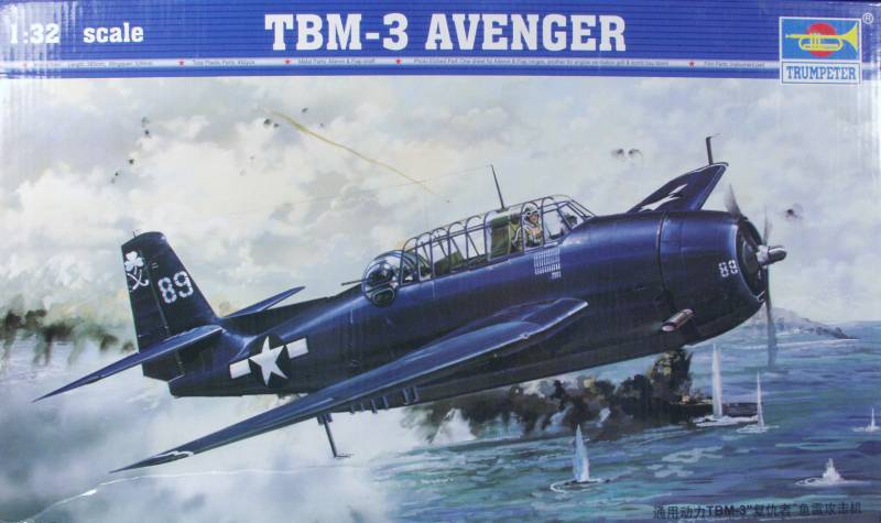
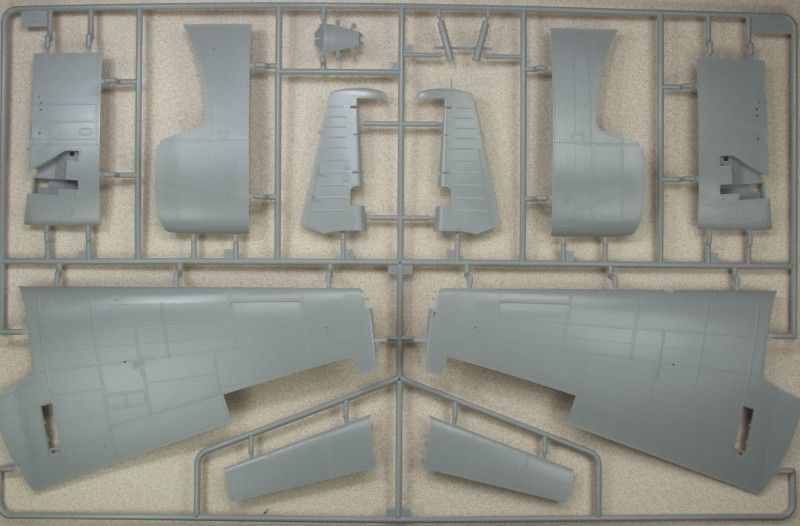
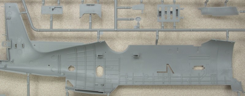
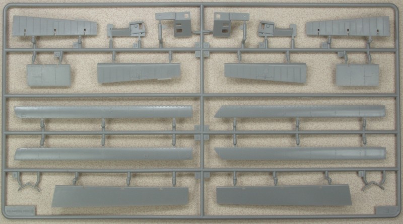
The Trumpeter kit comes in a huge top open tray type box that is packed to the top with sprues. The top and bottom are both made of heavy cardboard. The bottom of the box has a divider and a partition and at one end a box big enough for a good sized 1/72 kit. Inside it are the turret clear part, the cowling, tires, instrument panel, parts for the folding mechanism for the wings, two photo etch frets, the control surface hinge pins, a film for the instrument panel dial face and a piece of string listed on the parts map as rope. The divider at one end separates the clear parts sprues which are individually bagged and the partition traps the small sprues to keep them from shifting around under the larger sprues. All in all quite a packaging job. For all of that I still has a couple of the clear parts come off the sprues in shipping as well as one from one of the other sprues. Altogether there are twelve sprues and all but two sets of duplicates are in individual bags. The duplicate sprues are bagged together, The parts are molded in light gray. The surface finish is glossy and the surface detail consists of recessed panel lines, rivets and fasteners with a few raised details where applicable. I found only a few faint wisps of flash here and there. Mold alignment is good and the mold separation lined are mostly light. Looking over the main airframe parts, and that's a lot to look at, I found no obvious surface defects. I did find some mold release on one of the wing halves so washing the parts would be a good idea, at least the airframe parts any way. as for ejector pin marks it looks like those on the inside fuselage halves were kept out of sight and I didn't see any on some of the usual suspects such as gear struts and inside the gear doors. However there are plenty to be found. Several bulkheads with detail molded on both sides have them on one side. How visible they will be remains to be seen. Also if you drop the flaps the upper wing surface structure in that area has them as well so be prepared to deal with a few of them.
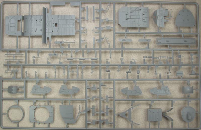
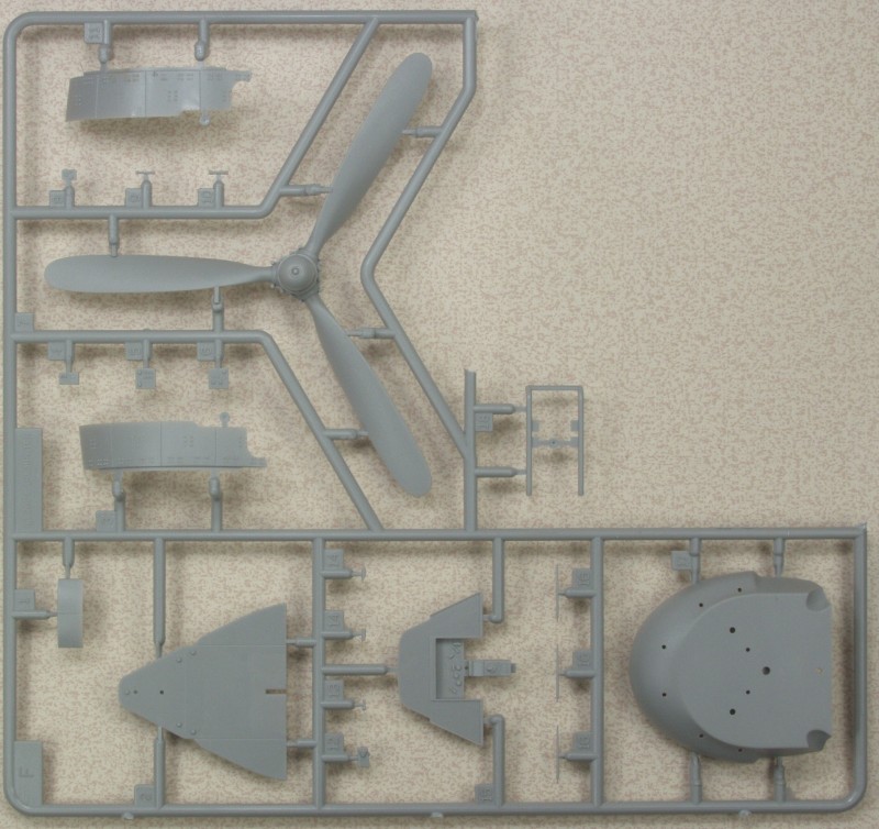
From a detail standpoint, like most of their 1/32 scale kits, it has a very detailed engine assembly which takes up the better part of the first two pages in the instruction manual. The engine accessory section has close to 25 parts alone including some photo etch. Most of the intake manifold pipes are individual parts and the exhaust manifolds divided into two parts. All of these are on the rear of the engine and this kit does not have a clear cowling nor are there any open panels so all of this will be pretty much hidden. The engine needs only ignition wires to look complete. There are optional open or closed cowl flaps.
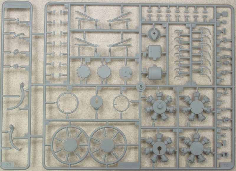
The interior is very well detailed as most of it is visible under that large canopy. The instrument panel is a clear part with a film sandwiched between it and the forward bulkhead to provide instrument dial detail. Photo etch belts and harness are supplied as well as some photo etch levers. The interior assembly takes up about three pages in the instructions. The bomb bay is also heavily detailed and the bay doors have photo etch inner panels that will look quite nice if you leave them open. The bomb bay can be configured with a fuel tank, four bombs or a torpedo. The gun turret is another model within a model taking up a page and 2/3 in the instructions. The tail wheel bay is well detailed also. The side access door to the rear of the fuselage is a separate part and can be left open.
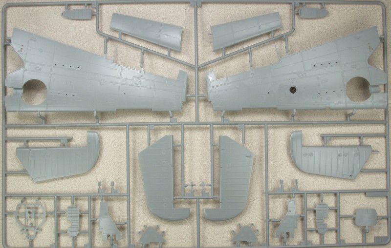
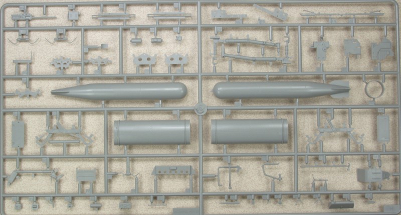
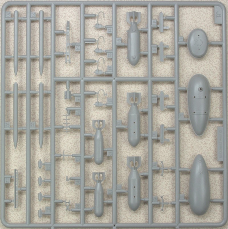
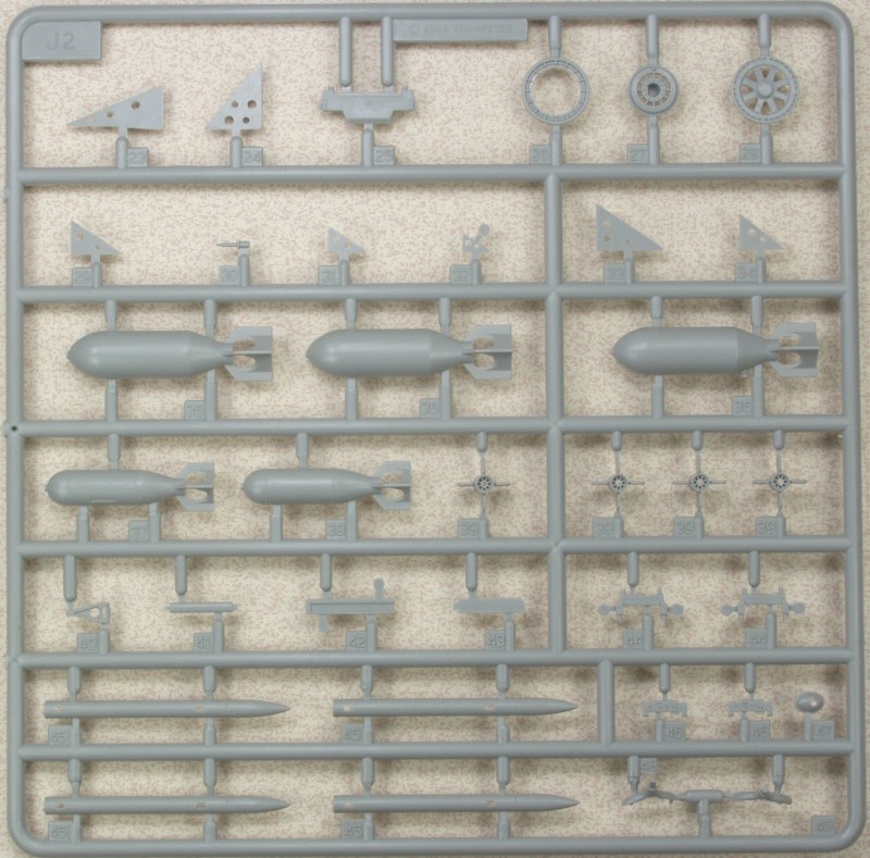
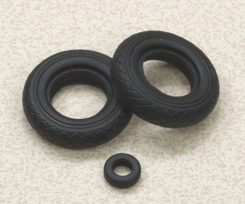
All of the control surfaces are supplied separate including the flaps and they use Trumpeter's photo etch hinge system. Personally I don't care for it as it can be exceedingly tedious to get together. The wings can be displayed folded or extended. There are two stiffeners that pass through the fuselage, one near the front of the wing, the other near the rear to provide a solid mount for the wings. If you plan on having them extended, reinforcing the joint on the inside is highly recommended. The wings have detailed gun bays and the arming hatch is separate and can be displayed open. For under wing stores one can choose between two bombs or two drop tanks and there are zero length launch rails for 8 rockets under the wings. The landing gear are nicely detail but could use some brake lines. The tires are supplied as vinyl with separate hub and inner and outer rims. The canopy can be opened or or closed. This is a huge kit and I have only hit the highlights detail wise. Lets look at the parts.

There are two of the next sprue,
And two of the next sprue.
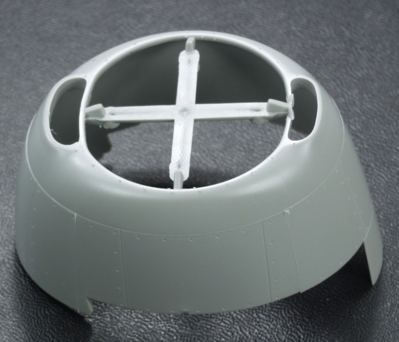
The cowling was packed separately.
The vinyl tires.
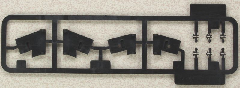
These are parts that are used for the wing fold, not sure why they are molded black unless they are made from a stronger plastic.
The first photo etch fret has seat belts and harnesses, interior panels for the bomb bay doors, radiator screens for the cowling and gap strips for the wing joint on the top of the wing.
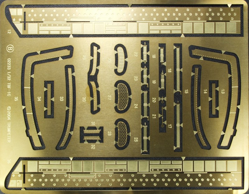
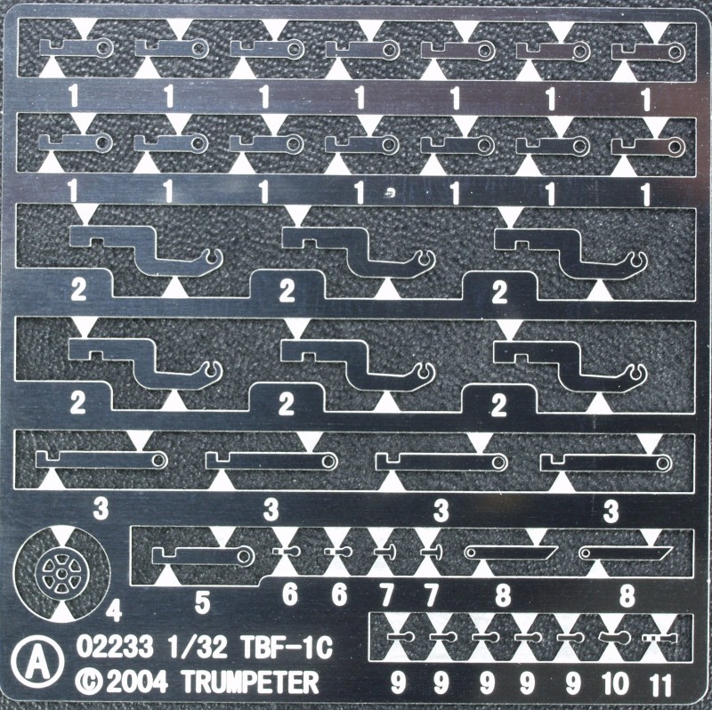
The second photo etch fret had all of the control surface hinges and levers for cockpit detail.
The clear parts are thin and clear with well defined frame lines. Parts are supplied for open or closed configuration.
![]()
![]()
The clear turret glass is very nice and packed separately.
![]()
The clear instrument panel.
![]()
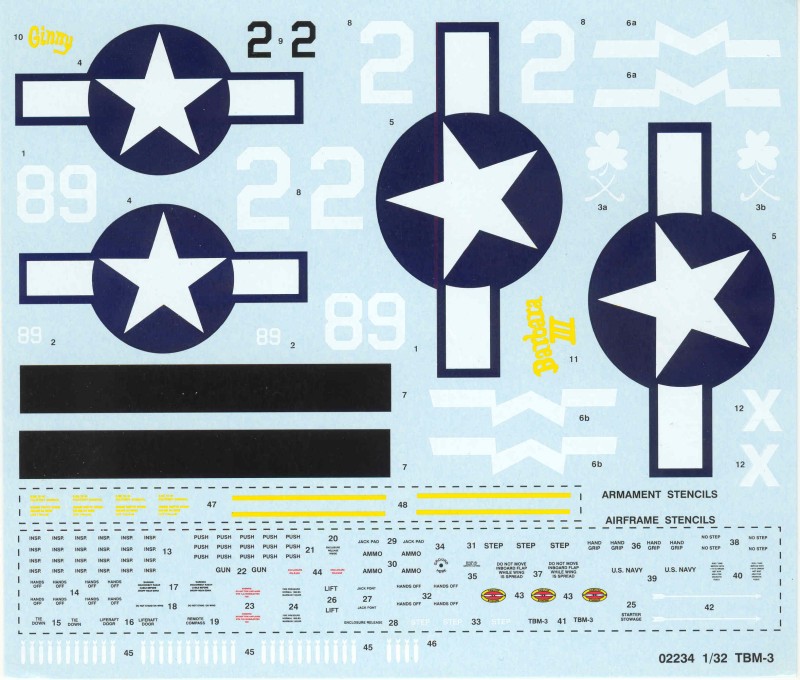
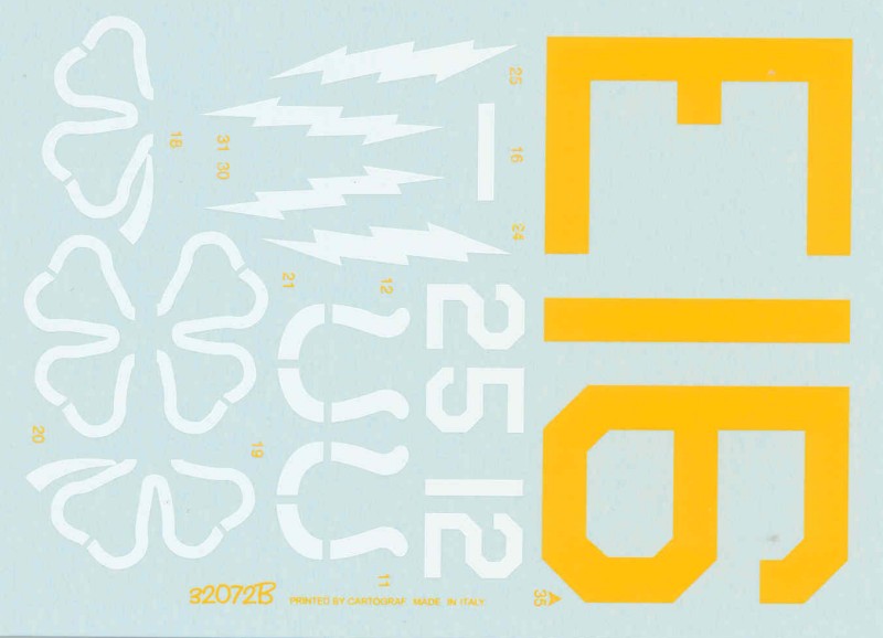
The decals are thin and glossy and in register. Difficult to tell how opaque the white lettering will be over a dark surface. Wing walks, stencils and prop decals are included. Markings for two aircraft are included; white two of VT-51, U.S.S. San Jacinto, summer 1944, painted in three color finish and #89 of VC-94, U.S.S. Shamrock Bay, early 1945, painted overall glossy sea blue.
The instructions are a 28 page booklet, A4 size in landscape format. The first page has general instructions and icon chart. The next two pages are the parts map, the balance of the booklet are assembly diagrams in 61 steps. Colors called out are Gunze numbers and as always don't trust them to be correct, check references if possible. A separate sheet printed in color on glossy paper and the painting and marking instructions.
After Market Goodies
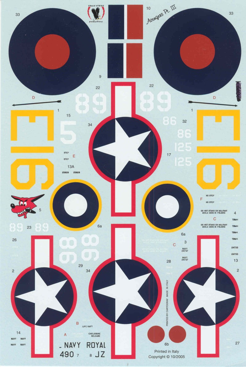
With a kit like this I like to have a lot of options for markings so I picked up this set by Eagle Strike (32073) The set provides markings for five aircraft although for three of them the you must use the stars and bars from the kit. Only one of the five is for a TBM-3, from VC-88 U.S.S Saginaw Bay, march of 1945. There is one TBM-1, CVE-59 U.S.S. Mission Bay, one Avenger II, Royal Navy, one TBM-1C, VT-7 U.S.S. Hancock, and one TBM-1C, VC-76, U.S.S. Petrof Bay, 1945. The decals are thin, glossy and in register. They are printed by Microscale and should work well. If you like the -1C options Trumpeter did a boxing of that version as well.
Conclusions
With 492 parts this kit is both massive in size and scope. From all indications there are no fit issues although with the amount of interior detail involved, joining the fuselage halves might call for extreme care and test fitting. In a kit of this complexity just keeping track of the parts can be an issue as well as locating them on the large number of sprues. This kit is one of Trumpeter's better kit and perhaps at least in my eyes its only down fall is the use of the photo etch hinge system for the control surfaces. Because of its complexity I can not recommend the kit to beginners but anyone with modest experience should be able to build the kit if they pay attention to the instructions. Recommended if you have the space and time.
Links to kit build or reviews
Note:
Both of the reviews linked below are for the TBM-1C kit which except
for some minor details is identical to the -3 version. The in box
review points out a few areas where there are issues detail wise if
things like this cause you to lose sleep at night.
An in box review can be found here and a build/review can be found here.
References
History courtesy of Wikipedia
Back to the 1/32 U.S. Aircraft Page