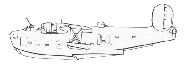
Consolidated logo

PB2Y-5

The PB2Y was the end result of a contract placed by the Navy in July of 1936 for a large four-engined maritime reconnaissance bomber flying boat. Designated the Model 29 by Consolidated and XPB2Y-1 by the Navy. The XPB2Y-1 flew for the first time on December 17, 1937, powered by four 1,050 h.p. Pratt and Whitney Twin Wasps. Initial trials revealed serious lateral instability. Initially auxiliary vertical tail surfaces were fitted and although some improvement resulted it was found necessary to redesign the entire tail assembly using twin tails with circular end plate vertical surfaces. The XPB2Y-1 was eventually delivered to the Navy and after completing trials became the Flagship of the Aircraft Scouting Force.  

While the aircraft was acceptable to the Navy their budget prevented them from ordering more until March of 1939 when six production aircraft were ordered under the designation PB2Y-2 with the first of these being delivered on December 31, 1940. The hydrodynamic characteristics of the XPB2Y-1 left much to be desired and Consolidated had taken the opportunity provided by the Navy's lack of funding to redesign the hull making it substantially deeper than the prototype and the circular tail fins were changed to an oblong configuration similar to those of the B-24. Power was increased on the 
PB2Y-2 using Twin Wasps rated at 1200 h.p. Named the Coronado the PB2Y-2 carried a crew of nine and had a defensive armament of six 50-caliber machine guns. The PB2Y-2 was the fastest version of the Coronado with a top speed ranging from 224 m.p.h at sea level to 255 m.p.h. at 19,000 ft. The six were used primarily for experimental purposes as they lacked self-sealing fuel tanks and armor protection for the crew.

One of the six was converted as the XPB2Y-3, the production PB2Y-3 having been ordered in November of 1940. The 
PB2Y-3 had self-sealing main fuel tanks and 2000 lb. of armor protection for the crew and the defensive armor was increased to twin 50- caliber machine guns in bow, dorsal and tail turrets and  50-caliber machine guns in each of the beam positions. Later PB2Y-3's were equipped with surface search radar installed in a housing aft of the flight deck.  A total of 210 PB2Y-3's were built with the last one being delivered in October of 1943. Ten of the Coronado's designated PB2Y-3B were delivered to the British under Lend-Lease which were intended to be used by RAF Coastal Command but ended up being transferred to Transport Command and were used to fly freight across the Atlantic and between Africa and the West Indies. Thirty one others were converted by Rohr Aircraft Corporation for the transport role under the designation PB2Y-3R. Part of the conversion included replacing the Twin Wasps with two speed superchargers to single stage low-altitude engines rated at 1,200 h.p. at sea level. The propellers of the inboard engines being four-bladed and the outboard being three bladed. Additionally all military equipment was removed and the bow and tail turrets openings were faired over.

One PB2Y-3 was experimentally fitted with Wright 2600 Cyclones as the XPB2Y-4. Following the successful power plant modification of the PB2Y-3R, other -3 were converted to the low-altitude engines under the designation PB2Y-5. The re-engined patrol bomber featured an increased fuel capacity with the normal fuel load increased from 1,580 gallons to 2,512 gallons, which provided a range with an 8,000 lb. bomb load to 1,640 miles. Other-3 conversions with the low-altitude engines had all the military equipment removed and were used as ambulance aircraft in the Pacific under the designation PB2Y-5H.

The Kit


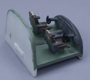
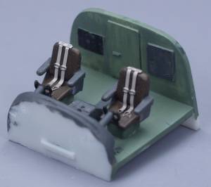
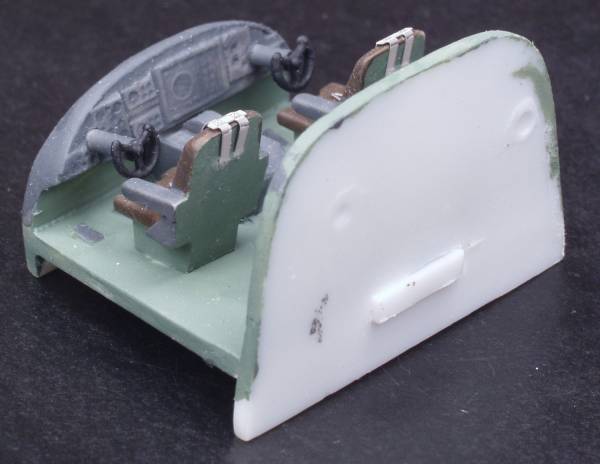
 Mach 2 kits have a mostly bad reputation as being some of the worst short run kits on the market, usually displaying sink marks on the wings and fuselage, huge ejector pin stubs on the inner surfaces, rough surface texture, terrible clear parts and flash every where. This kit seems to be one of Mach 2's better attempts. While the surface still has some roughness and irregularities there were no sink marks that I could see and the engraved panel lines seemed to be uniform and didn't disappear as on some of their other kits. Still lots of ejector stubs and the small parts are still flash laden and the clear parts could be better. Little in the way of interior detail is provided, a bulkhead, floor, seats and control columns. The box doesn't state what version the kit is and the instructions are labeled PB2Y-2, however a -2 two it isn't. The -2 lacked the turrets, had totally different beam positions, had a large blister on the top where the dorsal turret is located, did not use the radar housing above and behind the cockpit and didn't have the four-bladed props on the inboard engines.  The kit can best be used to represent a -5. The -3 could be done by replacing  the inboard propellers with three bladed units.

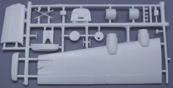
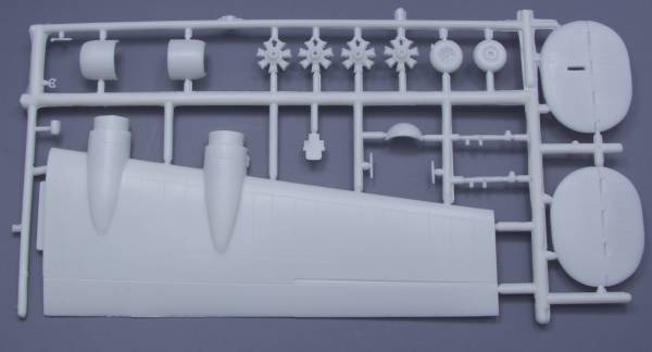
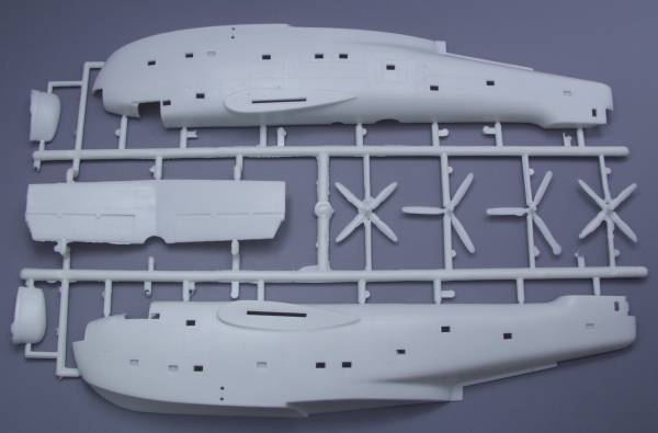
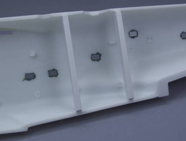
Lets take a look at what's in the box. There are five sprues of white plastic. Two sprues are nearly identical with bottom wing halves and various other parts, another nearly identical pair have upper wing halves and various other parts and a third has the fuselage and various other parts. Total parts count 87. See below...


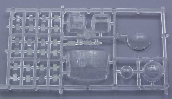
There is one sprue with clear parts if you can call them that, typical of most Mach 2 kits. Future may help them some. Unfortunately there are no after market vacuformed replacements available. Parts count 32 for a total of 119 in the box. See below...

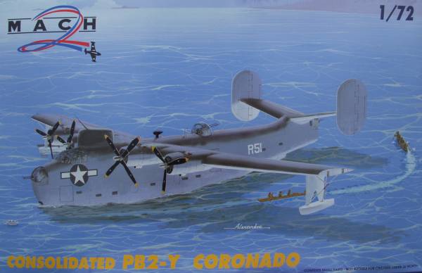
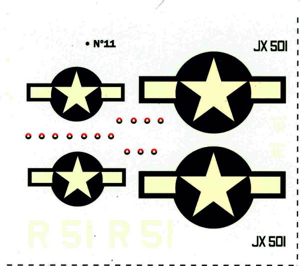
The decal sheet has the markings for the aircraft shown on the box top. The painting instructions show the colors and markings for an RAF aircraft but notes that roundels and fin flashes are not included. Other than the Star and Bar and the aircraft number the only other markings supplied are the manufacturers decals for the props. The decals look OK but I have no experience with Mach 2 decals so I can't comment on them. The color has been adjusted to make the lettering visible. See below...

The instruction sheet consists of a single A4 size page with various sub assemblies shown on one side and painting and lettering shown on the other. There are only a couple written notes on the assembly side which indicates where most of the small parts go but nothing showing the fuselage, wing or wing to fuselage assembly so you are pretty much on your own. The kit does come with beaching gear.

Conclusions

I test fitted the fuselage halves just out of curiosity. While they seem to match up pretty well, assembling them will be a challenge. One half has a bulge in the bottom of the fuselage just past the step that may be tough to fix and it looks like some addition bulkheads would be helpful to maintain the fuselage shape while gluing. As with all the kits from Mach 2 much labor is required to clean up flash from small parts and the lack of alignment pins makes assembly challenging. I would recommend the kit only to die hard seaplane fans and those with multiple limited run kit experience.

Links to kit build or reviews

None that I am aware of.

References

"War Planes of the Second World War Volume 5 Flying Boats" by William Green

The Build

 Main canopy was found to be nearly 1/8" wider than fuselage, fixing it will require modifying the kit piece to use as a master and vacuforming a new one. Due to the poor quality of the kit part this will be an improvement, however it just adds to the workload of an already tedious build.

Flight deck was not properly shaped and the fit in fuselage was not acceptable. I modified the deck and added styrene strip stock to each fuselage half to better align it during fuselage assembly. While trying to decide how much effort to put into detailing the flight deck I found a photo online that shows what the real cockpit looked like and it pointed to an error in Mach 2's parts. The photo shows that that the control wheels come out through the instrument panel in a manner like that of the Catalina and the B-24. In fact the control wheels look identical to those used in the Catalina. I really didn't want to make new ones since they won't be that viable once the fuselage is closed up, so...


I ended up using the supplied control wheels and mounted them on some 1/16" styrene rod. Then drilled holes in the instrument panel and mounted them so they would be in the proper relation to the seats. The seats themselves appeared to set too high and too far back. I shortened the lower portion of them and removed the mounting pads on the floor and placed the seats closer to the panel. The molded detail on the panel in no way shape or form matched the prototype so I just left it as it was and made no effort to dress it up any. If I was younger and steadier of hand I might have been tempted to add some additional detail in this area but I was pushing it as it was. I did put photoetch harnesses on the seats.  See below...


Tail pieces and wings halves aligned reasonably well but some time was spent sanding the mating surfaces on a sheet of sandpaper to insure a good fit and to thin the trailing edges some. After I had them glued together I wish I had thinned them more.

The fuselage needed some top to bottom spacers as one fuselage half sagged a bit near the top center. These were made from 1/8" x 1/4" styrene stock. The ends needed to be contoured to fit the fuselage. I also needed to add a shim of .020" where the supports met one side of the fuselage as it was thinner on one side than the other. See below...


I did not like the supplied small windows as they didn't fit well and were not clear, and also did not fit any where near flush. I made new glass for these from some clear stock I had for vacuforming. They were cut to fit the window openings then held in place with scotch tape from the outside so that they would be flush with the outer surface then a heavy coat of Future was applied to the inside. This forms a bead around the perimeter of the window and hopefully will keep it in place. If there are any gaps around the outside, they will be filled with clear parts cement.

I gave some thought to using after market engines but decided I didn't want to dump another $40 into this kit so I cleaned up and used the kit supplied parts. After removing the flash and painting they looked acceptable to me.
Another major glitch. The point of attachment for the tailfins to the tailplane. These should have mated at an angle to allow the tailfins to be vertical. They don't. One would have worked great if the rudders were to be mounted like those on the Mariner the other was molded at an angle but in the wrong direction. Tabs were cut off and the ends of the tail plane sanded to the correct angle plus shaped to fit the contour of the tailfins, then a new styrene block attached to mount the rudders.

Back to the Flying Boats page

Last updated 5/10/08