
Mitsubishi
G3M2 'Nell'
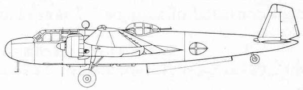
The Mitsubishi G3M series got it's start from a non-competitive specification that was issued to them on the recommendation of Admiral Yamamoto during the time he was serving with the Naval Bureau of Aeronautics. The specification called for a land based twin engine long range reconnaissance aircraft. The result of this was to serve as an aerodynamic prototype possessing the necessary performance required from a future attack bomber. The resultant aircraft (Mitsubishi designation Ka-9) possessing a clean air frame with a wing featuring flying control surfaces similar to those used by Junker's aircraft of the time, and twin fins and rudders. It demonstrated exceptional maneuverability and handling characteristics and achieved a maximum range of 3,265 nautical miles. The results of the flight test program were received with enthusiasm by the Navy which resulted in a new specification being issued to Mitsubishi calling for a fully developed attack bomber.
The resultant aircraft used the wings from the Ka-9 and a new wider fuselage. Corrugated panels on the wings were replaced with smooth skinned panels. The tail surfaces were enlarged and the landing gear simplified and strengthened. As the aircraft was intended to operate in support of naval units, the main offensive weapon was the torpedo, carried under the fuselage with no provisions for an internal bomb bay. This new aircraft (Mitsubishi designation Ka-15) made its first flight in July 1935. It was soon apparent that the aircraft was equal to most foreign aircraft of the time. Within a year twenty additional prototypes were built and despite the loss of one aircraft, the test program progressed smoothly. The prototypes were built in a variety of configurations with different engine and propeller configurations. In June 1936 it was put into production as the Navy Type 96 Attack Bomber Model 11 (G3M1). The production aircraft featured a redesigned canopy and internal equipment changes. Even though the G3M1 exceeded most of the Navy's original requirements, this variant saw only limited service as an improved version of the Kinsei engine allowed a further increase in performance.
Powered by two Kinsei 41 or 42 engines the G3M2 Model 21 differed only in minor internal details and increased fuel capacity. On 14 August, 1937, a week after the start of the second Sino-Japanese conflict a group based in Formosa sent its G3M2s against targets in mainland China and despite poor weather, flew 1,250 miles over water and made the first trans-oceanic bombing raid in aviation history. Soon thereafter the G3M2s were moved to bases on the mainland where they mounted raids deep into mainland China. However, operating beyond the range of their fighter escorts, the bombers suffered heavy losses due to wholly inadequate defensive armament. In 1940 Nakajima began manufacturing the Model 21 under a Navy production contract.
As
a result of pressing requests
from operational units Mitsubishi designed the G3M2 Model 22 with a
much revised defensive armament set up and various equipment changes
including a license built Sperry automatic pilot and radio direction
finding units. When hostilities with the United States began in
December 1941 the Japanese Navy had 204 G3M2s operating in first line
units and 54 in second line units. The bombers took part in operations
against Wake Island, the Philippines and the Marianas and on 10
December, 1941, sixty G3M2s and 26 G4M1s succeeded in sinking the two
British battleships the HMS Prince of Wales and HMS Repulse of Malaya.
As Japanese forces moved swiftly through the Southwest Pacific
islands,
so did the G3M2s. However they had already been replaced on the
Mitsubishi assembly lines by the G4M1 leaving Nakajima as the sole
manufacturer. By 1943 few of the G3M2s were still operating in their
intended roles with most surviving aircraft serving until the end of
the war in second line units as glider tugs, bomber trainers and
maritime reconnaissance aircraft often fitted with search radar. A
total of 1,048 G3Ms were built including prototypes.
The Kit
The Koster Aero
Enterprises G3M2 as you have probably already guessed is a vacuform
kit. While I would prefer an injection molded kit as of this time no
manufacturer has blessed us with one in this scale. The kit comes in a
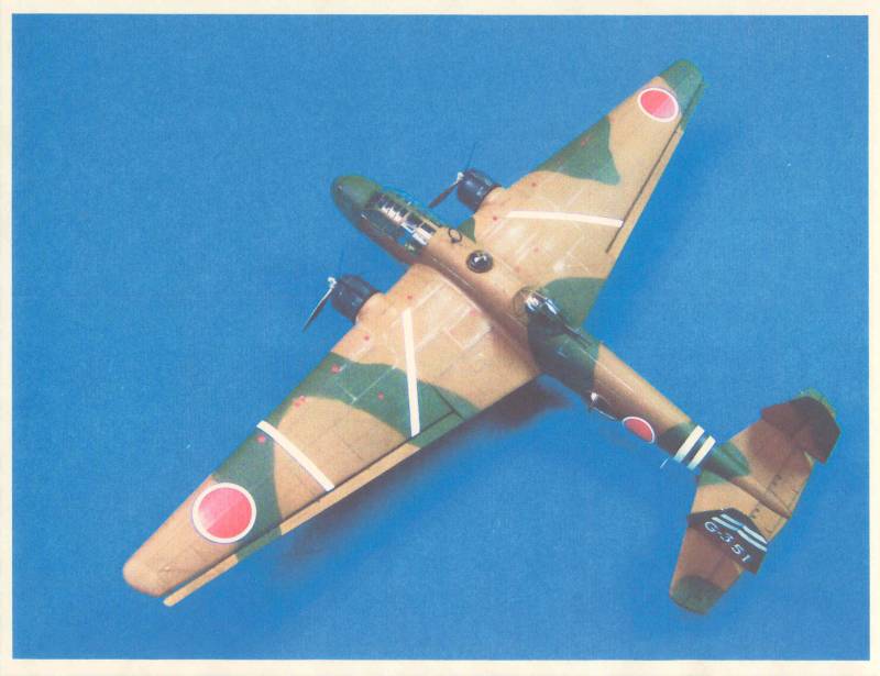
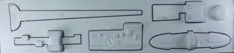
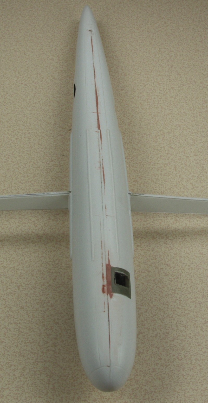
medium sized plain corrugated box. The
photo above is included inside the box along with three sheets of
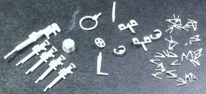
vacuformed parts. Also included in the box is a pair of cast metal
propellers, a zip lock bag of additional cast metal parts, a zip lock
bag full of cast resin parts and a vacuformed set of clear glazing.
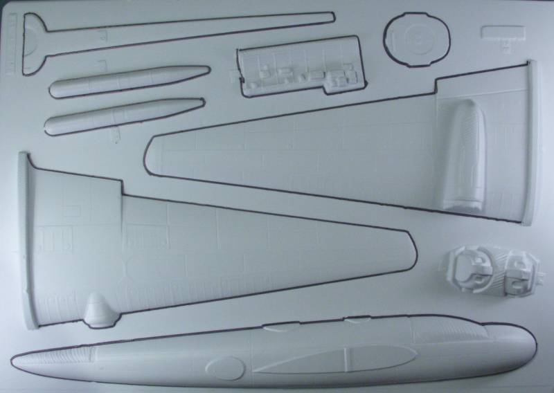
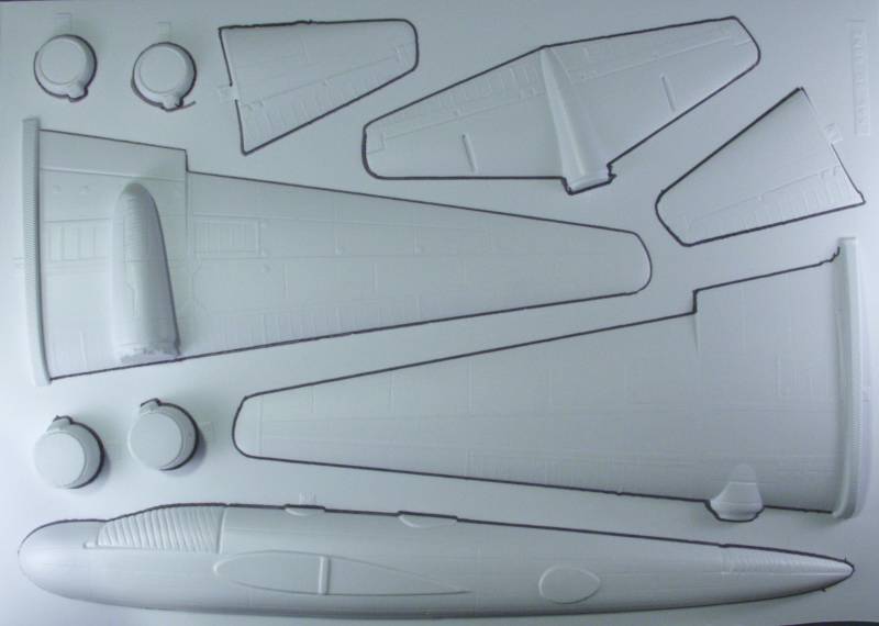
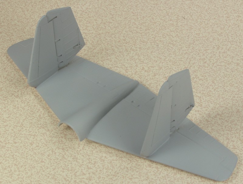
Koster uses heavier plastic than many makers of these
types of kits which makes for a bit sturdier construction. Two of the
three sheets are good sized and have the primary air frame parts, a
bulkhead, one wing spar, torpedo, engine cowlings and some internal
side wall detail. A smaller third sheet has the other wing spar and
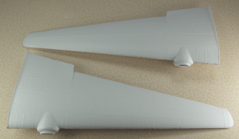
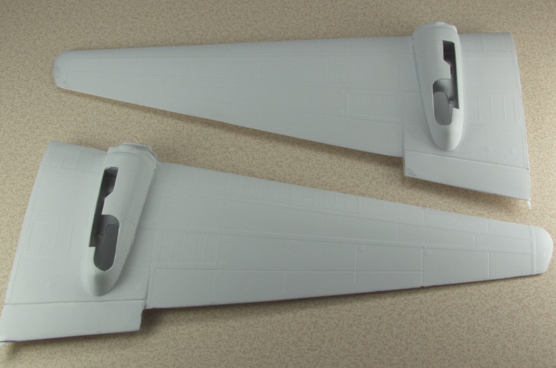
some additional internal details. In spite of the heavier gauge
plastic
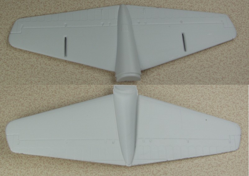
used the surface detail is very nice with recessed panel lines a
raised
detail as appropriate.
While the detail is not up to the standard expected with injection molding it is some of the nicest I have seen on a vacuformed kit. The fabric control surfaces are a bit overdone to my eye but no worse than many injection molded kits. As is the case with many vacuformed kits invariably the plastic gets stretched very thin in some places especially on very detailed parts and such is the case here and on some parts some additional strengthening may be needed. The internal side pieces are a mixed bag, the one has so much detail that most of it ended up being rather soft and lacking detail while the other turned out much better. Still a little soft but probably acceptable once installed inside the fuselage. I suspect I'll will be temped to cut the detail away on one side and replace it with some scratch built parts with sharper edges and more defined details. In the photos below I have outlined the parts with a magic marker not only to make them stand out more but as the first step in preparing the parts. For those new to vacuform kits I will supply a link at the end of the review that may give you an idea of what is involved. See below.
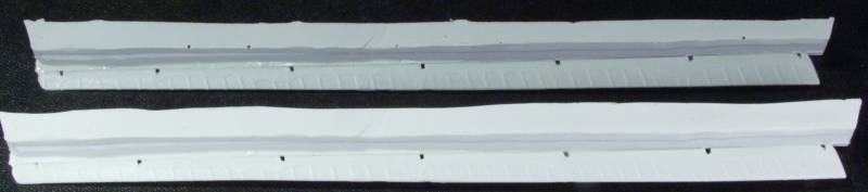
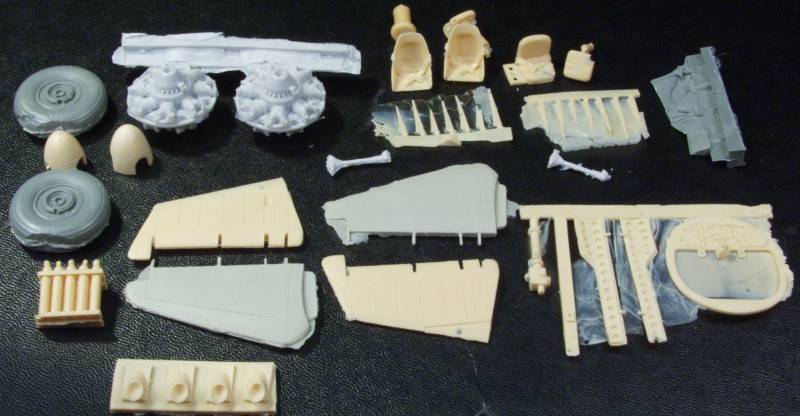
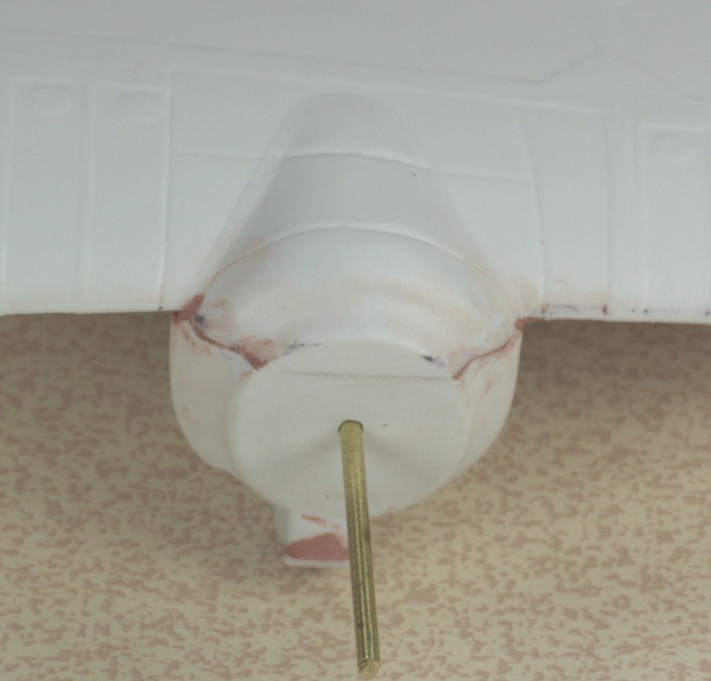
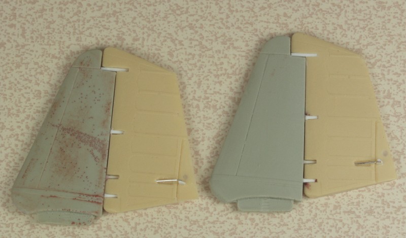
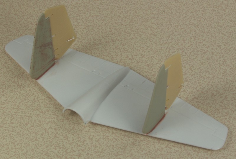
The G3M series aircraft were equipped with flying control surfaces on the wings much like those used on Junkers aircraft like the Ju 52 and Ju 87. These would be tough to do as a vacuform part and in this kit these are supplied as a resin part. The castings were quite good in my kit with few if any casting defects although both are a bit warped. Once removed from their casting blocks a warm water dip should take care of the warps. See below.
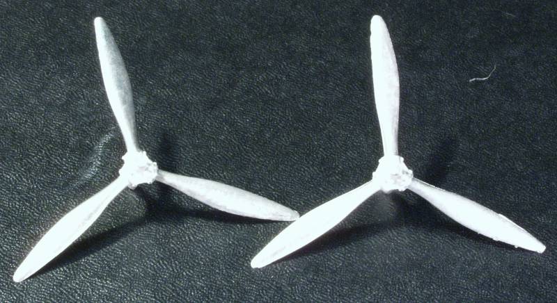
The propellers are provided in cast soft metal and look quite nice needing only some light clean up of flash.
The landing gear is also done in metal and again is quite nice. Like many cast metal part some of them may need to be tweaked a bit to get them straightened out.
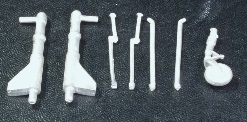
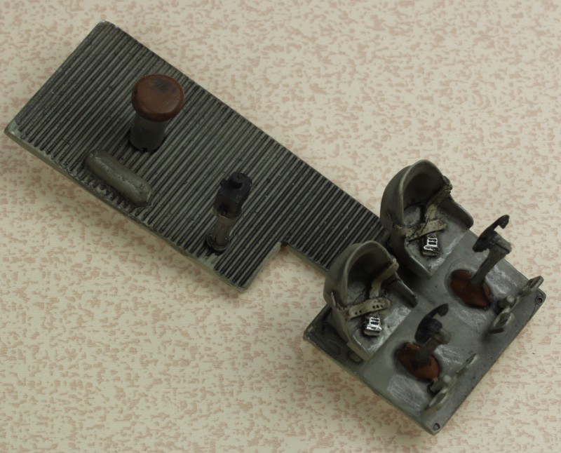
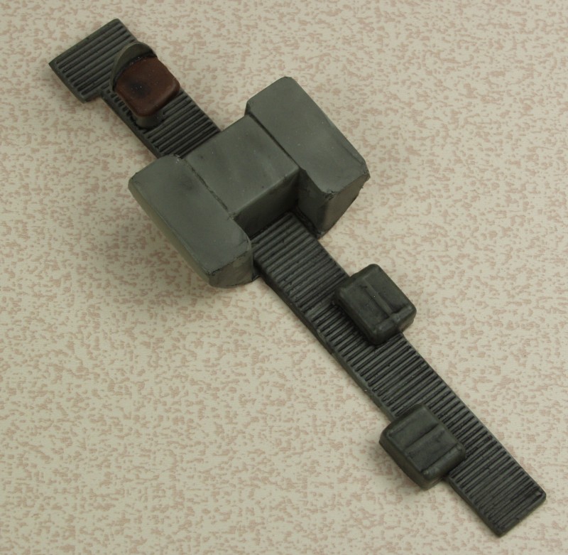
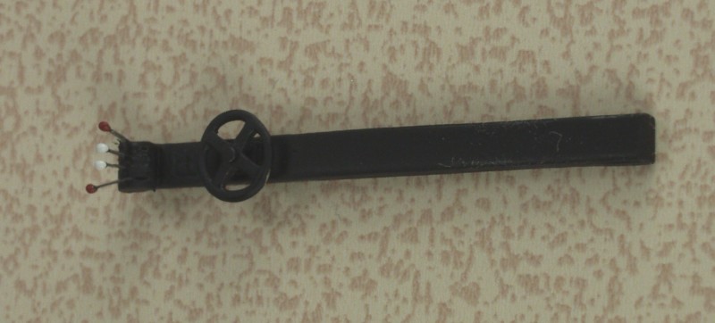
The balance of the metal parts are for the guns, an ammo drum, DF loop, antenna, pitot tube, trim wheel, control wheels, rudder pedals and all those 'V' shaped parts which are intended to be the push rods for the resin engines. Those must have been a pain to cast and look to be even more of a pain to clean up and install. I may decided to skip that and make them out of thin wire instead. These parts are for the most part nice and should be that hard to clean up and straighten. The guns would probably look better with some hypodermic tubing for barrels.
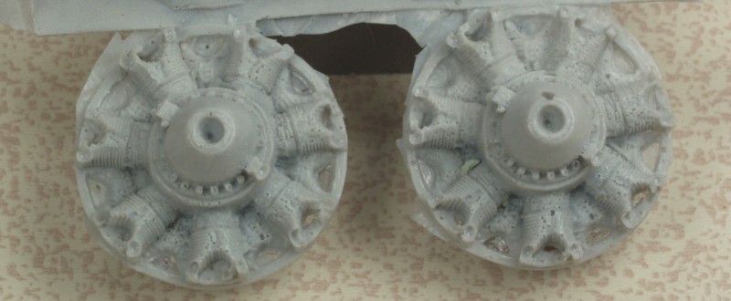
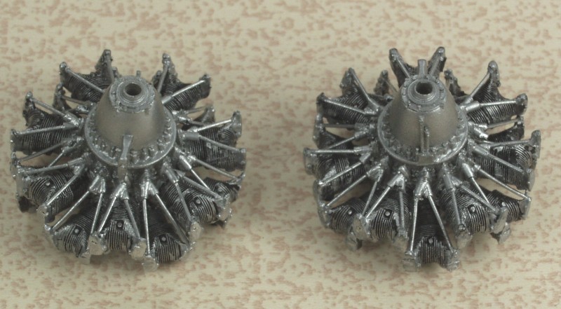
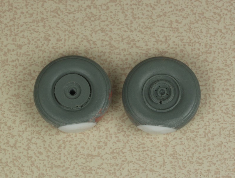
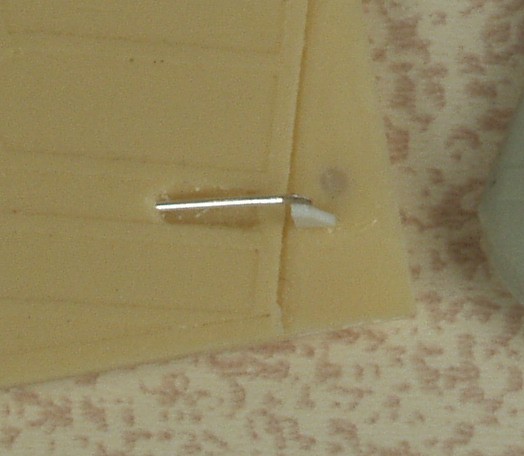
The resin parts shown below are some what of a mixed bag. Molded in three different colors of resin. The engines which at first glance didn't look too bad but mine were marred with a numerous air bubbles on the front side. Once painted and buried in the cowlings they might be passable but I would recommend replacing them with quality resin replacements from Vector. The wheel assemblies are a bit rough and to my eye a bit too flat. The Prop spinners are good. The fins and rudders are nice but do have a few bubbles to fill. The oxygen tanks are nice as are the seats but again the seats will require a bit of bubble filling. The exhaust stubs are nice as are the gear doors and the bulkhead with the instrument panel but they will require a bit of clean up. The wedge shaped parts are the mounting parts for the flying control surfaces and these look like they could be a challenge both to clean up and install. The other two parts are the control columns.
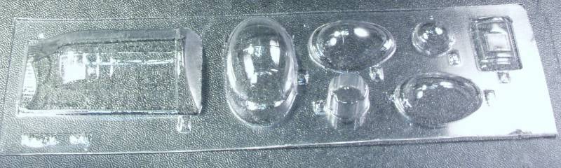
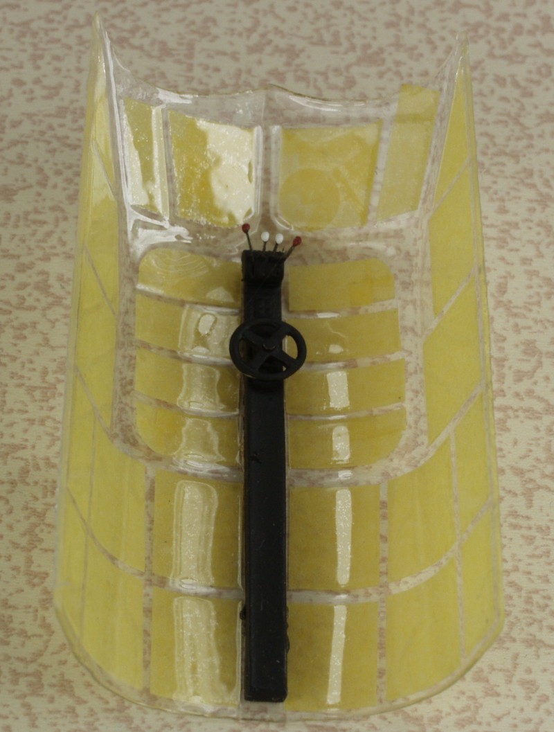
The clear parts are quite clear and since they are molded out of heavier material than is the norm they are a bit more sturdy and easier to work with in my opinion. Although it doesn't show well in my photograph the frame lines are pretty well registered and shouldn't be that hard to mask.
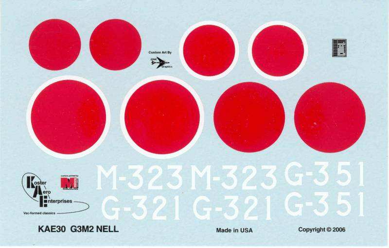
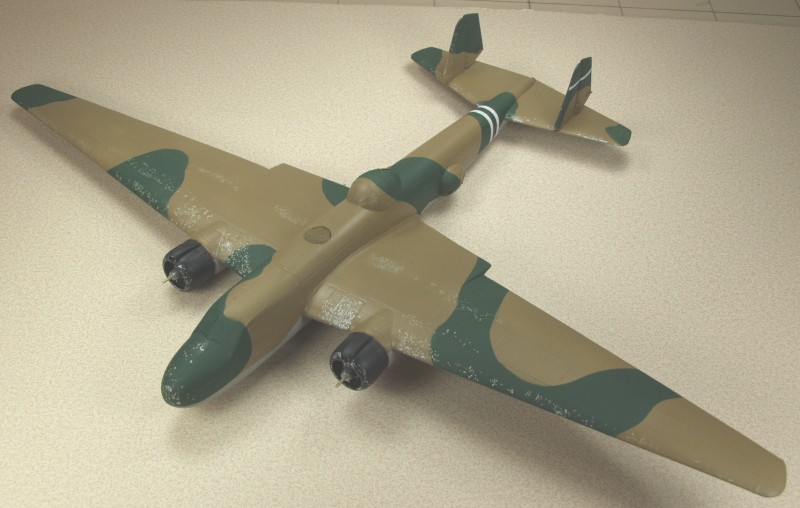
The decals appear thin and are well registered. I have used a few of the decals supplied by Koster before and have not had any issues with them. They appear opaque. Markings are supplied for three aircraft with similar but slightly different paint schemes. See Below.
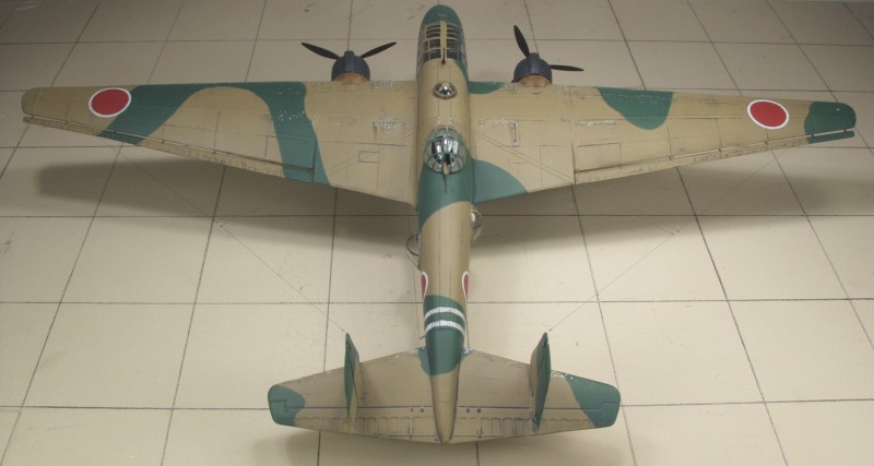
The instructions consist of two 8 1/2" x 11" pages printed on both sides. Three of the sides have the assembly instructions and the forth has painting and decal instructions. This page is printed in color, the others in black and white. While the instructions are pretty basic everything is there that need to be. Two other color photos are included, one is an overhead view of a completed model and the other an eye level view that looks like it was meant to be a box top cover as it lists the number of parts included and other information you would expect on the box. It may have been left off mine since it was delivered by mail.
After Market Goodies
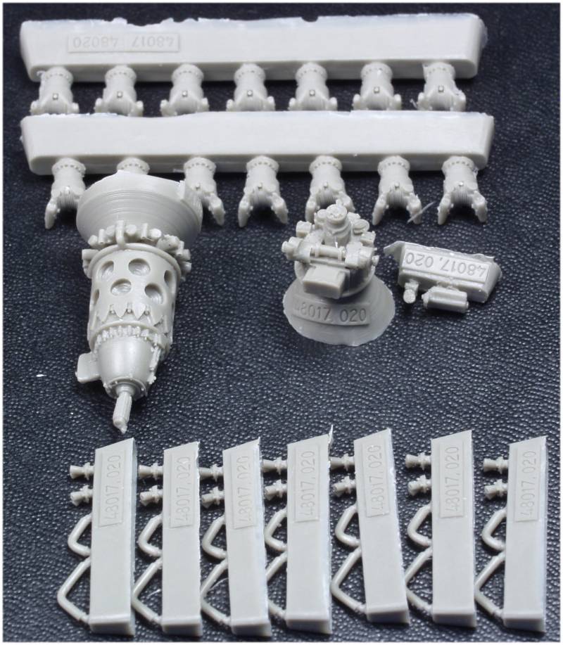
None specific to the kit but I did want to replace the kit engines. I would not recommend Engines and Things for these if available as they may not be any better than the kit parts and may in fact be worse. Fortunately Vector makes a kit of the "Kinsei" engine, their number 48-017 and it was only a matter of finding them in stock. These are pretty much like all vector engine kits, superbly molded and miniature kits in themselves. The issue with using these on many injection molded kits is that the engines are to scale but the cowlings are usually far from scale thickness so you need to file away lovely detail in order to make them fit, I'm hoping that will not be the case here but only time will tell. The engine kits include parts that won't be seen so if you are not opening up panels or displaying them unmounted some parts can be left off. The instructions are printed on a small scrap of paper but are adequate. If you need more detail photos of preserved engines can usually be found on line.
Conclusions
OK, vacuform kits may not be your thing and if I had a choice I wouldn't go that route but right now it it the only choice in this scale. Koster kits are some of the best vacuform kits around and while I wouldn't recommend it to a first time vacuform builder it certain is a good choice for someone who is familiar with the them and wants a 1/48 scale Nell. For some good basic information on building vacuform kits look here.
Links to kit build or reviews
An in box review can be found here.
References
Japanese Aircraft of the Pacific War by R.J. Francillon
Back to the Miscellaneous Japanese Page
The Build
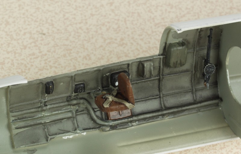
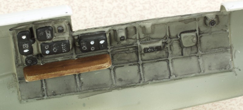
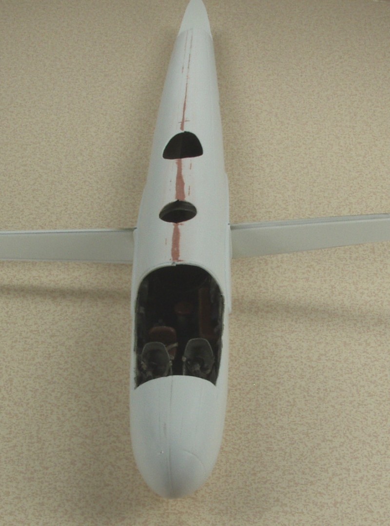
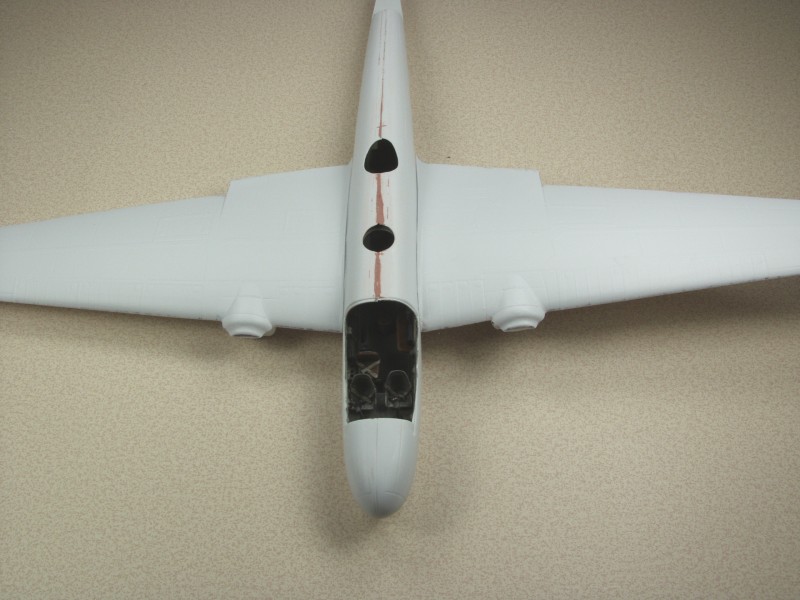
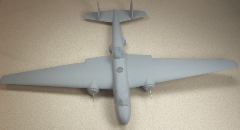
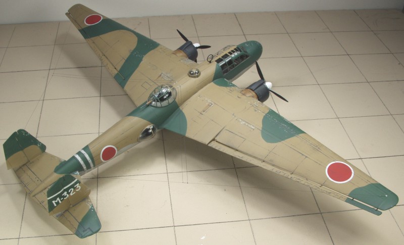
Like most kits assembly starts with the cockpit. Well not exactly, in this case the first thing was to get all the piece removed from their molding sheets an the thickness of the base sheet sanded off of all the parts. I did this a few at a time so it didn't become a total drudge although it went faster than I anticipated. Unlike some bare bones vacuform kit Koster supplied a decent level of interior detail. My wash got a little sloppy and some of my detail painting left something to be desired but the clear parts aren't that clear and all we're looking for is an impression that there is something there. Detail like this is not well reproduced with vacuforming and if I had been able to find better interior references I would have done some scratch building here. I did add a few detail PE parts from an Airscale cockpit detail set. Many of the resin parts in the kit were a disappointment being so full of air bubbles or poorly cast as to be unusable.
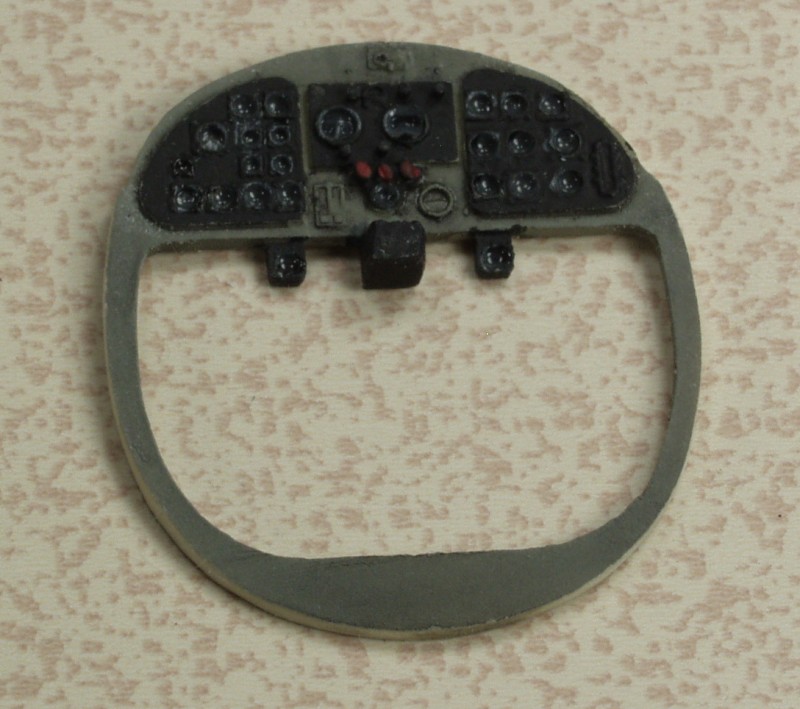
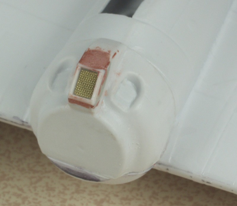
I considered doing more with the instrument panel but in the end it sits back under a cowl and is very difficult to see so I only put some Future in the dials and painted some switches.
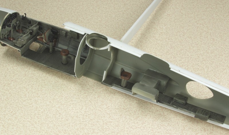
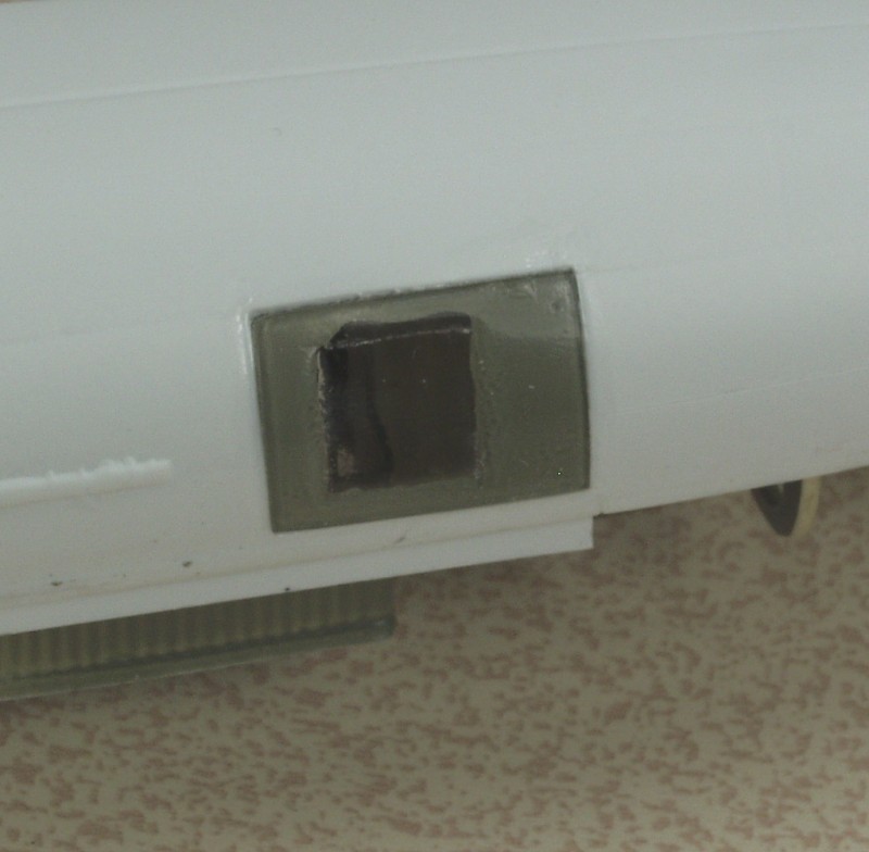
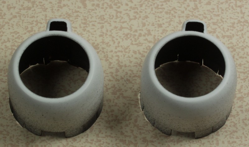
The openings in the cowls was cut out very carefully as the cowls were very thin, almost paper thin back by the flaps making them look quite realistic.
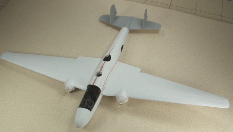
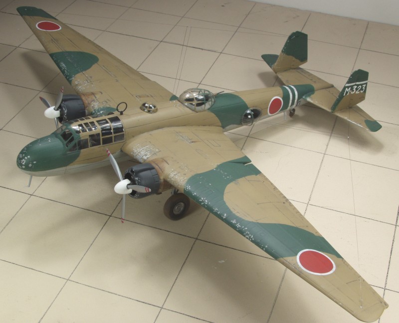

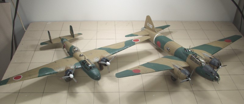
Just as a comparison a photo next to the recently completed Betty, though not as rotund the Nell is still a good sized aircraft.
In conclusion I have to say this was actually a positive experience. It would have been better had the resin and decals not been an issue but over all I have had much worse experiences with injection molded kits. Don't expect all vacuforms to fit or be as well detailed as Bill Koster's.
Back to the Miscellaneous Japanese Page